Altair Virtual Wind Tunnel for ultraFluidX 2022 Release Notes
Highlights
Virtual Wind Tunnel 2022 brings significant improvements when working with STL files and adds features towards the needs of aero-acoustics simulations.
Highlights include:
- Improved performance with STL files
- Higher frequency sampling through sub-time step support
- User friendly output control with an updated microdialog and table view
- Improvements to support fan noise simulations
- Visualization support via HyperWorks CFD Post
- Improved batch capability
New Features
- Improved performance with STL files
- A new, lightweight triangle-based model representation dramatically improves STL file I/O performance, especially for large models. Model import and load times are now twice as fast. Vwt/stmod file save time is three to four times faster for large model files. File sizes and application memory usage have been reduced to half the previous usage.
- Improved batch capability
- Virtual Wind Tunnel can now be launched in batch mode with and without the GUI. Batch mode enables you to import a model, import and apply a full simulation template, and export simulation files. These output files can subsequently be run with ultraFluidX.
Enhancements
- Higher frequency sampling through sub-time step support
- ultraFluidX allows much finer output data from refined mesh regions in
the form of fractional output intervals. These are now specified in
floating point format. These are automatically rounded to the nearest
supported fractions. A new microdialog shows the output interval
specified as 0.25 below that corresponds to the fraction ¼. The
corresponding physical frequency is also shown as a visual aid.
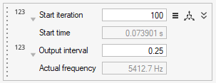
Figure 1. - Improved output control
- Post-processing data output controls now allow unit-based inputs, in
addition to solver-based iterations. Start time for recording outputs
can be specified in physical time or solver iterations. High frequency
sampling via sub-time steps is supported through three input choices:
- Fractional output intervals
- Mesh refinement levels
- Frequency-based input
- As shown previously, the microdialog for outputs has been enhanced so
you can select your preferred input mode. Choosing the clock icon on the
top left will allow you to a input start time in seconds, as shown
below. Instead of fractional output interval, you can specify the mesh
refinement level by selecting the mesh icon in the left center to set
the correct fractional output interval.
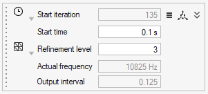
Figure 2. - Alternatively, you can select the Hz icon to directly specify your
preferred sampling frequency in Hertz. This input is automatically
rounded to the closest fraction supported by the solver and mesh
refinement level. The actual sampling frequency and fractional output
interval are shown right below the user requested target frequency.
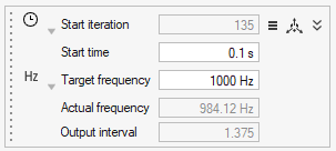
Figure 3. - While all outputs support this new microdialog design, monitoring
surface has a subtle difference. Since it doesn’t support fractional
output intervals, calculations are rounded to whole numbers and mesh
refinement level selector is unavailable. In addition, it uses a
drop-down menu to select Visual and Summary output modes. Previously,
the Visual and Summary outputs were stacked one below the other.
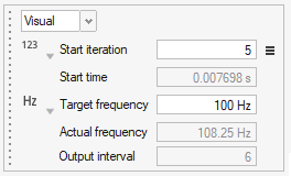
Figure 4. - The Output Table view allows you to work with all this information in
the same window. Multiple outputs can be selected in this view which
makes bulk changes easy to perform.
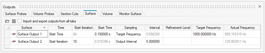
Figure 5. - Simulation mode to support Fan Noise simulations
- A simulation mode has been introduced in the Run dialog that can be used to indicate you are performing a fan noise simulation. This tells the ultraFluidX solver to automatically reconfigure default settings from external aerodynamics to fan noise and saves the user from having to do them manually.
- Smooth ramp up for fans
- The simulation can now be smoothly ramped up with user specified
iterations in the Run dialog. This smoothly
increases the fan rotation speed and inflow velocity for the Wind
Tunnel.
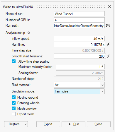
Figure 6. - Support for precision and scientific notation for Probe output data
- As part of enhancements needed to improve fan noise simulations, probe output data is now written out in scientific notation and the output data precision has been increased to eight significant digits. You can override these settings in the Output Controls panel.
- Improved default settings
- The default window-averaging window size is now computed as a function
of inflow velocity and object length.
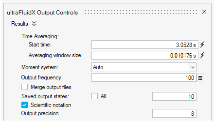
Figure 7. - Visualize results with HyperWorks CFD Post
- The uFX results files can now be visualized in HyperWorks CFD Post. The
Show Analysis button will prompt you to select
*.case or *.sos files that
are then loaded into HyperWorks CFD Post. HyperWorks Desktop will need
to be installed separately for this to function seamlessly. This
replaces Fieldview which is no longer available from within Virtual Wind
Tunnel.
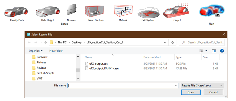
Figure 8. - Support for binary STL files
- Binary STL files can now be imported into Virtual Wind Tunnel. Note that binary STLs do not support multiple parts or names in a single file. All triangles in a single binary file are imported as a single part.
Known Issues
The following known issues will be addressed in a future release as we continuously
improve performance of the software:
- Modifying units on importing STL/NAS files.
- In rare occasions selecting the split intersected parts advanced option for a fan overset mesh volume can cause errors.
Resolved Issues
- Divide by zero errors are protected in case of zero inflow velocity.
- Run settings are saved correctly in the *.vwt database format.
- Probes created on overset volume no longer gets transformed into Point objects.
- Gap finder tool has been removed.