Highlights of FluxMotor2022.1
1. Frame and shaft – A new thermal network
- Frame and end caps - Design
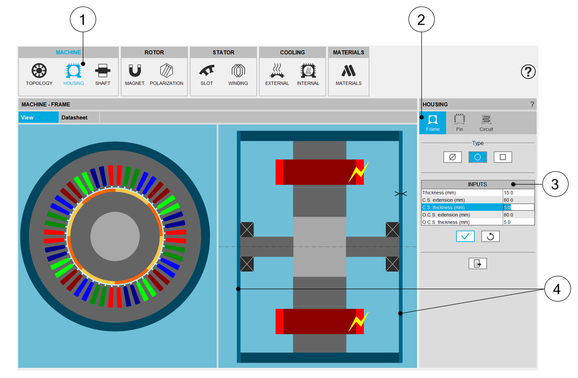
Frame / Housing design area – End caps and frame 1-2 Selection of the Housing subset: HOUSING panel. Settings of the frame and end caps dimensions 3 User inputs for defining the dimensions of the frame and end caps 4 The two end caps are considered separately from the frame and each of them can have its own dimensions - Frame and end caps – Materials
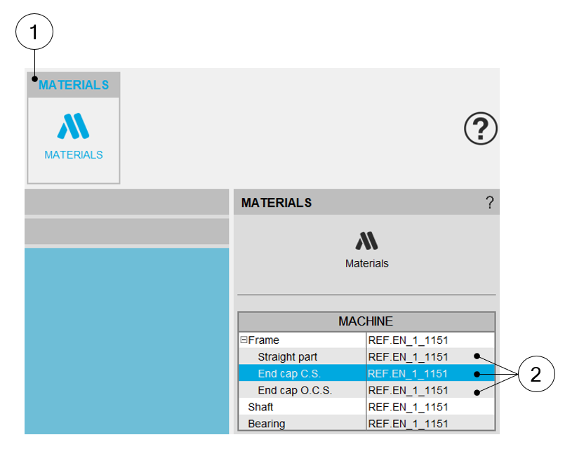
MATERIALS design area 1 Selection of the Material subset: MATERIALS panel (Click on the icon MATERIALS) 2 The two end caps are considered separately from the frame and each of them can have its own material - Internal cooling – New interface gaps
This panel allows describing imperfect contacts between the different components of the machine. The imperfect contacts are here modeled as a parasitic airgap between two parts, through which the heat must be conducted through to go from one part to the other.
The interface gaps are composed of air at the atmospheric pressure, at 20 °C, equivalent to 293.15K. For more information on material properties, please refer to FluxMotor® material database (“Materials application”).
In the new version, new imperfect contacts have been added in the machine:- The interface between the frame and the end cap – Opposite Connection Side
- The interface between the frame and the end cap – Connection Side
- Each bearing has its own interface gap thickness which is used to compute the corresponding thermal resistance of the considered bearing. These two values are used separately in computations.
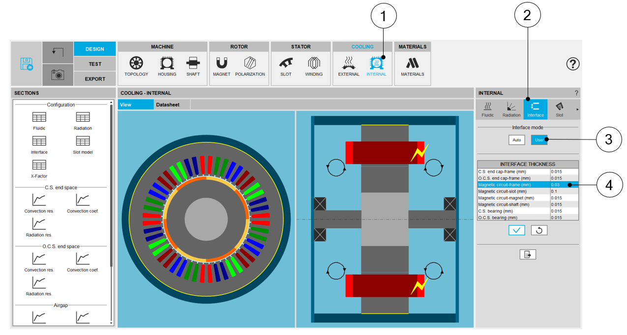
Internal cooling - Interface design area 1 Display the internal cooling datasheet, showing the thermal parameters defining the internal heat exchanges.
Display the axial and radial view of the machine.
2 Selection of the section “Interface” in which all the imperfect contacts between the different components of the machine can be set. 3 The user mode can be selected to define the interface thickness manually. 4 A list of interface thickness (imperfect contacts) is available. In this list new interface gaps have been added.
See illustration below.
Interface thickness between frame and end caps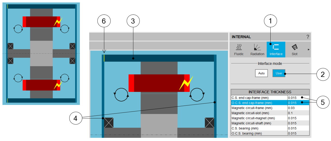
Interface design area – New interface thicknesses between frame and end caps 1 Internal cooling – Definition of the interface parameters 2 User mode to set the interface gaps manually. 3-4 Visualization of the Straight part of the frame and the two different end caps 5 Air gaps between the frame and the end caps can be set separately for both sides of the machine 6 The line which corresponds to the selected air gap to be defined is highlighted Interface thickness inside each bearings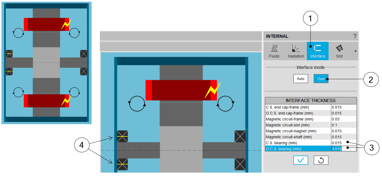
Interface design area – Interface thicknesses for bearings 1 Internal cooling – Definition of the interface parameters 2 User mode to set the interface gaps manually. 3 Air gaps to be set for both bearings at the Connection Side and at the Opposite Connection Side 4 The line which corresponds to the selected air gap to be defined is highlighted - Thermal resistance network – Frame, end caps and the external
fluid
The global resistance between the frame, the end caps and the external fluid is illustrated in the thermal resistance network shown below.
Three main paths extract the heat from the machine to the external fluid, corresponding to three main components: the straight part of the frame and the two end caps.
In the new version, the dimensions of the frame, the Connection Side end cap, the Opposite Connection Side end cap and their physical properties can be defined separately.
Note: Each of these paths extracting heat of the machine is composed of several thermal resistances in series:- The conduction through the material composing the part
- The convection and radiation occurring from the external surfaces of the frame
In this network, the convection resistances are a mixture of natural and forced components of the convection phenomenon.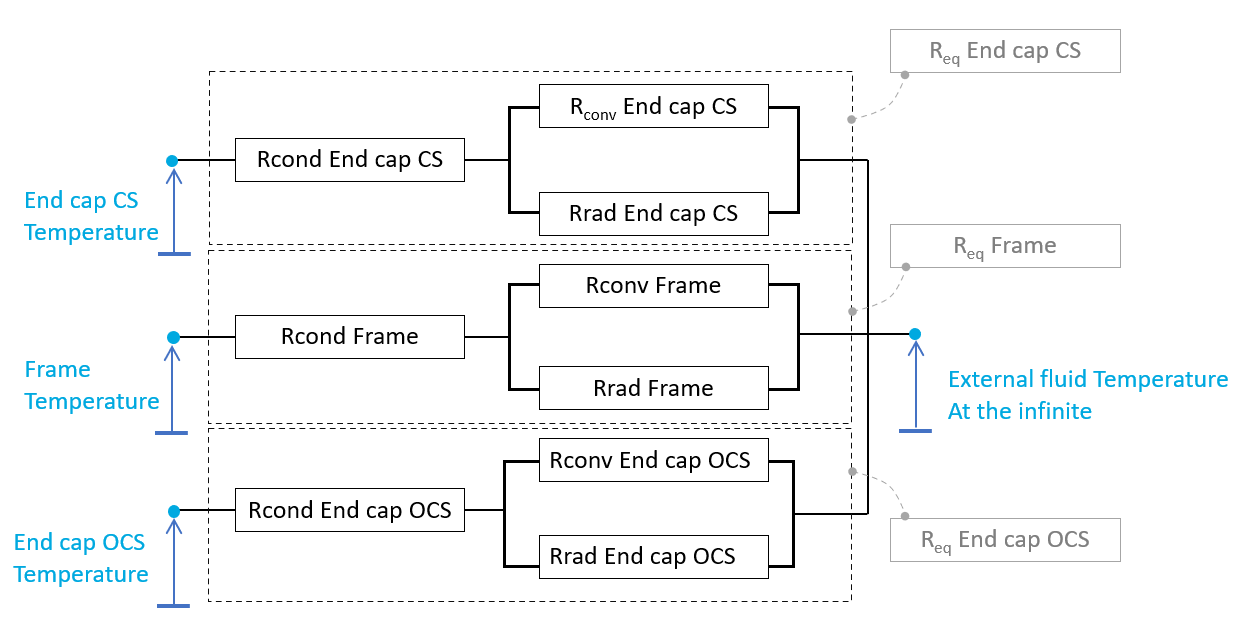
The global resistance between the frame and the external fluid - Thermal resistance network The equivalent thermal resistances defined above are integrated in the global thermal network. The part of this network corresponding to the end parts of the machine is described below.
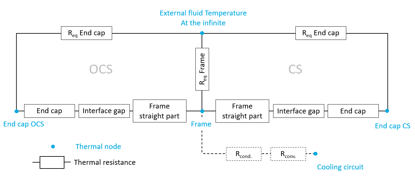
Thermal resistance network including the interface gaps between the frame and the end caps - A new general thermal resistance
network
Synchronous Machines with Permanent Magnets – Inner Rotor
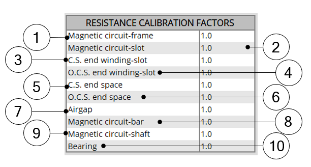
The following picture gives an example of a simple thermal circuit, including the main resistances corresponding to the default synchronous magnet machine, where the frame, the two end caps, the shaft and the bearings have been added.
The numbers on every resistance show what X-factor impacts this resistance value.
To keep the scheme simple, the radiation resistances are not represented there.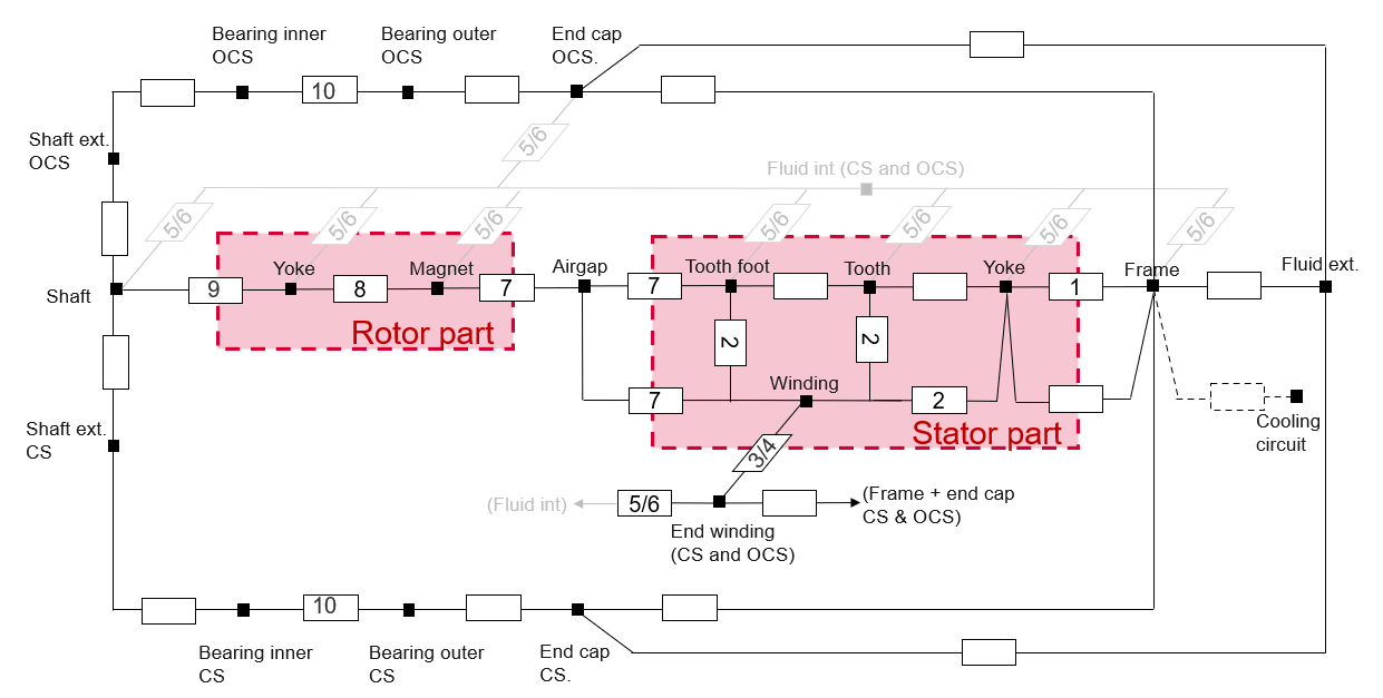
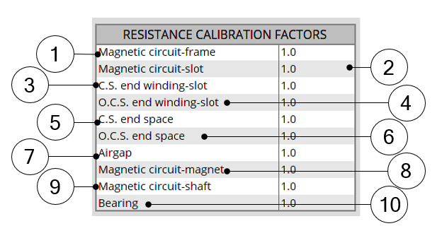
Thermal circuit – Relation with the calibration factors As illustrated the improvements in the new version deal with the following points:
- Additional thermal nodes for the two shaft extensions
- Additional nodes for the two bearing which can be considered separately
- Additional nodes for the two end caps which can be considered separately from each other and from the frame (straight part)
Note: The same improvement has been applied for the Reluctance Synchronous Machines – inner rotor and for the Induction Machines with Squirrel Cage – inner rotor as well.The corresponding general new thermal networks are displayed below.
Reluctance Synchronous Machines – Inner Rotor – New thermal network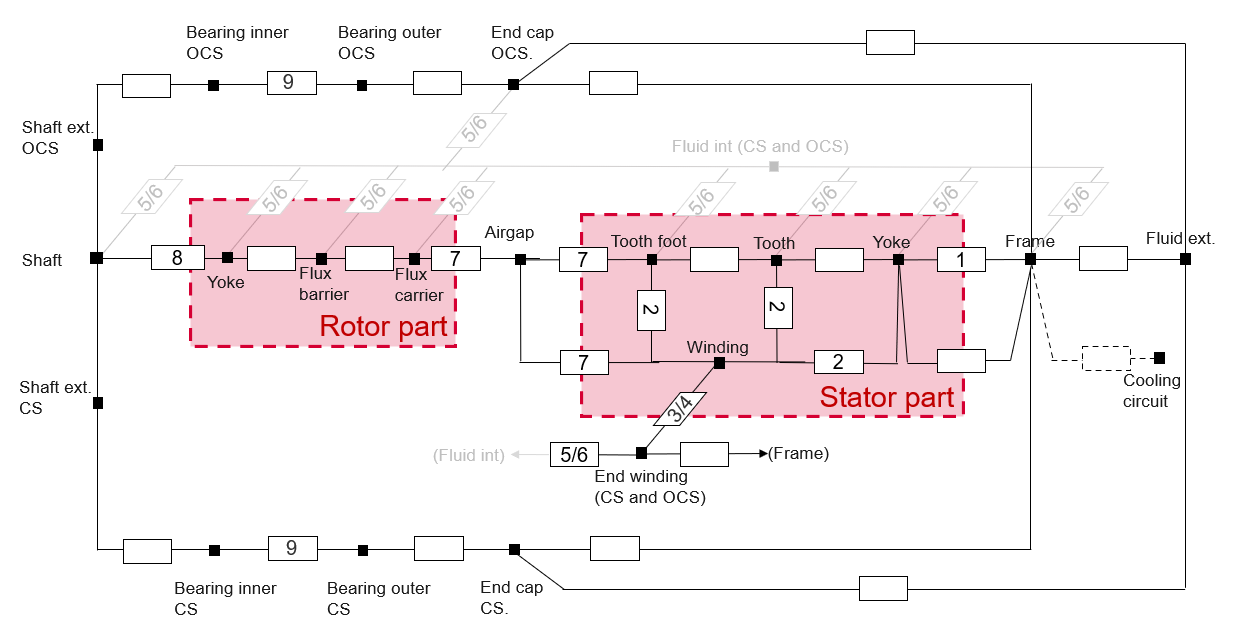
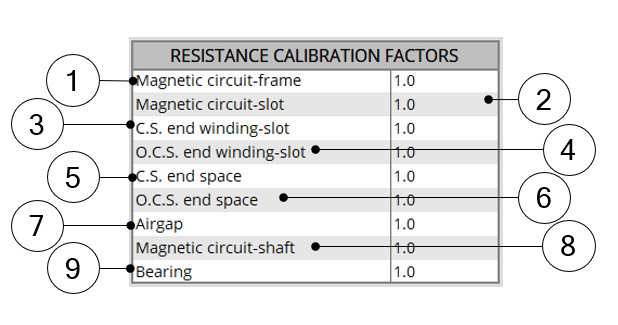
Thermal circuit – Relation with the calibration factors Induction Machines with Squirrel Cage – Inner Rotor – New thermal network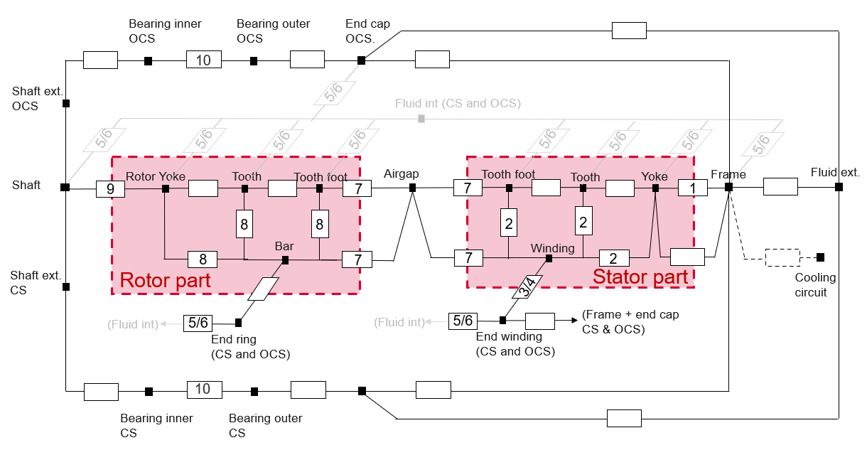
Thermal circuit – Relation with the calibration factors
2. A new "use case" for the winding definition expert mode
- What was the problem with previous version?
In the previous versions, while using the expert mode for designing the winding architecture, the user set the connection table by considering the number of duplications. A drop-down menu gave the possible choices of duplications based on the number of slots and poles.
Then, the allowed number of parallel paths could be equal to 2 times the number of duplications. Because it was assumed that two circuits - per elementary duplicated sector - could be represented in the connection table.
However, it was impossible to find how the winding was distributed between these two circuits.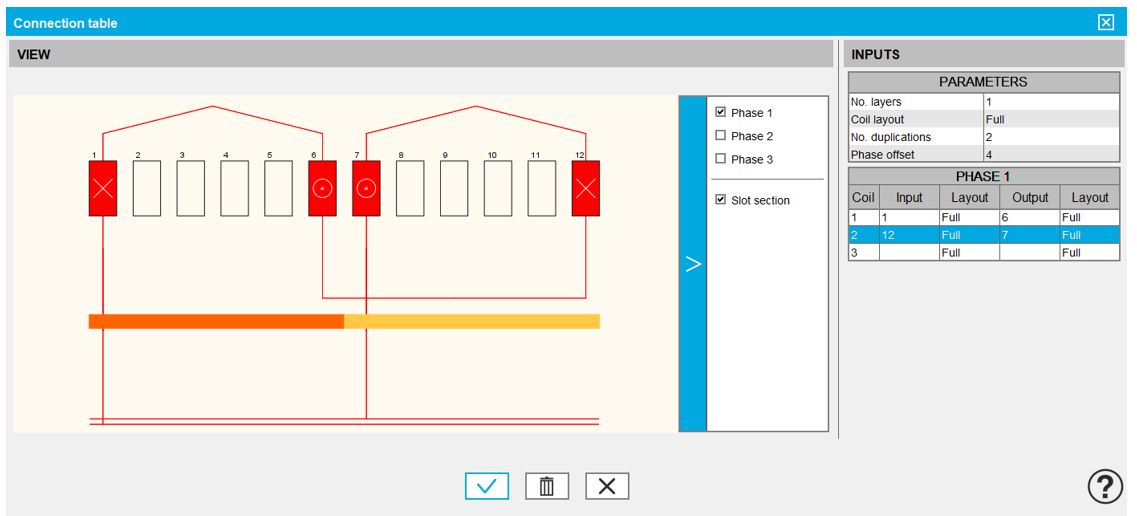
Dialog box for defining the connection table while using the expert mode Input and output of each coil must be defined. In that case 2 duplications are considered which means that only half of the winding must be defined.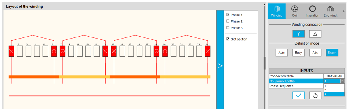
Layout of the resulting winding architecture Considering that the allowed number of parallel paths could be equal to 2 times the number of duplications, 4 parallel paths can be built.
However, in such case, one couldn’t represent the parallel paths and their connections with the circuit. The circuits' ends were not connected.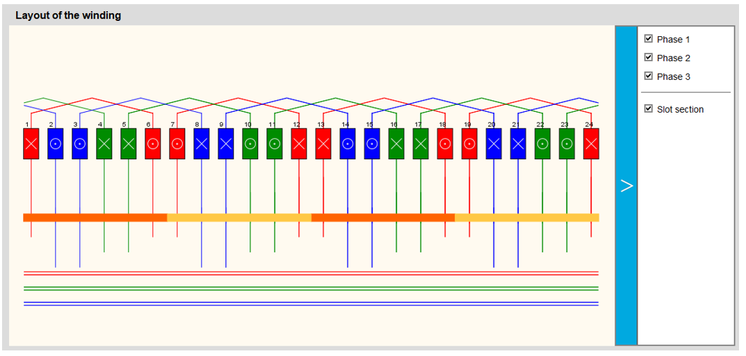
The circuits ends of the three phases were not connected - What is the new use case?
Since the last version (version 2022.0), the real distribution of the parallel paths in the winding is taken into account for performing the tests.
Hence, the previous configuration where it wasn’t possible to know how the parallel paths are distributed led to an error (Ref. FXM-14637). This issue has been fixed.
For the correction of this issue, it is required to know how the parallel paths were distributed. From now on, in the expert mode, to define the connection table, the user can define the number of circuits to be duplicated and he must fill in a connection table for each elementary parallel path.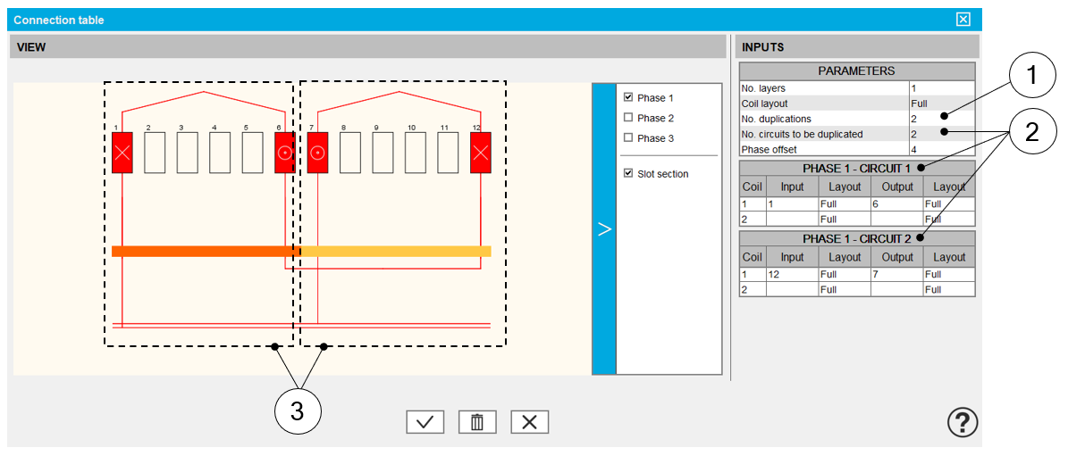
Dialog box for defining the connection table while using the expert mode 1 Definition of the number of duplications.
This number is computed and proposed to the user. It depends on the number of slots and the number of poles.
When the winding architecture to build is cut into several identical parts, the corresponding possible number of duplications is proposed (a short list).
By selecting the number of duplications, the user must define only 1/n of the connection table.
2 Number of circuits to be duplicated represent the number of elementary circuits to be defined inside each sector to be duplicated. In this example 2 circuits are defined in the represented sector.
This is why, there are 2 connection tables to be filled in. One for each circuit.
3 Representation of the two circuits inside the considered sector. Then, the list of possible number of parallel paths « No. parallel paths » adapts itself in function to the number of duplications « No. duplications » and to the number of circuits to be duplicated « No. circuits to be duplicated ».
Here is the resulting layout of the winding architecture below. There are always 4 possible parallel paths. But this time, these circuits can be well connected.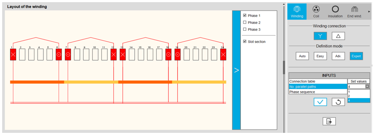
Layout of the resulting winding architecture Warning: Concerning, the motors built with previous version and for which the winding was initially defined with the expert mode, when these will get opened with the new version (2022.1), the user input « No. circuits to be duplicated » will be set automatically to 1 and only one parallel circuit is considered.Important:This modification is a problem for motors with a number of parallel paths « No. parallel paths » which is greater to the number of duplications « No. duplications » .
In that case, one must decided and modify the value of the « No. parallel paths » to make it relevant to take the value of the « No. duplications »
Important: This is done without any warning given to the user.
3. The GUI can be displayed in Chinese and Japanese languages
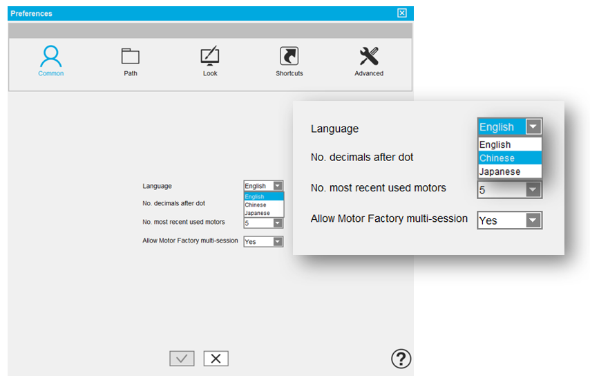 |
| User preferences – Selection of the language used for displaying the GUI |
 |
| User preferences – Selection of the language used for displaying the GUI |
- FluxMotor® GUI in Chinese – Example of displaying
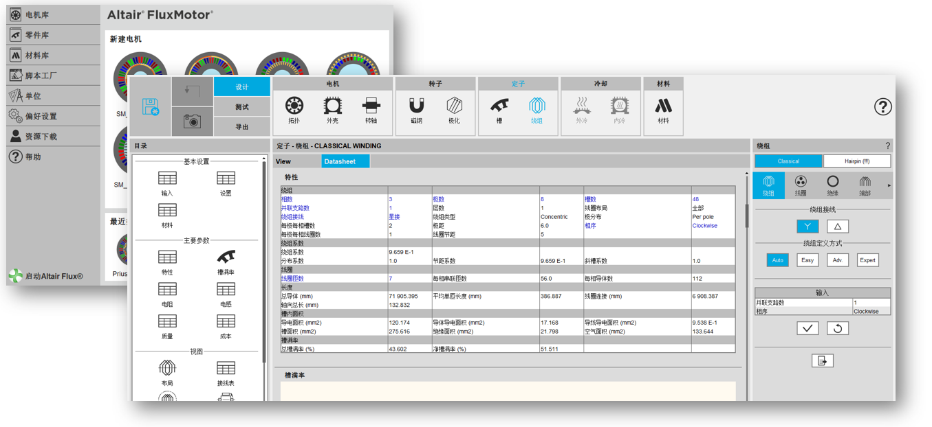
FluxMotor® GUI in Chinese – Supervisor and Motor Factory – Winding area - FluxMotor® GUI in Japanese – Example of displaying
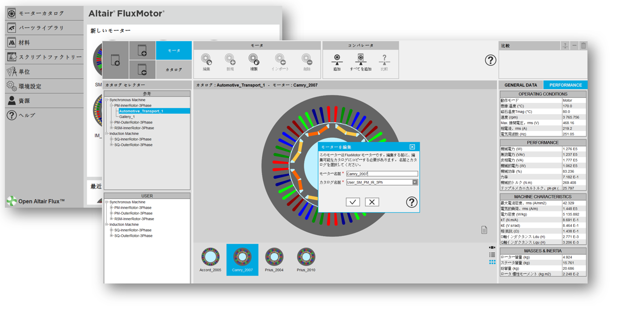 |
| FluxMotor® GUI in Japanese – Supervisor and Motor Catalog |
4. A new online user help guide area
The online user help guide framework of FluxMotor® has been modified to be consistent with what it is done for Altair® Flux® and for the other Altair® solutions.
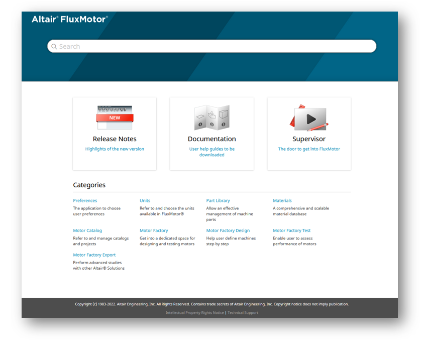 |
| Home page of the new online user help guide |
From now on the users need to use their Altair One login and password to open the online user help guide.
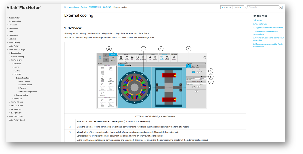 |
| Displaying of the online user help content |