 Package Modelica.Mechanics.Translational.Components
Components for 1D translational mechanical drive trains
Package Modelica.Mechanics.Translational.Components
This package contains basic components 1D mechanical translational drive trains.
Extends from Modelica.Icons.Package (Icon for standard packages).
| Name | Description |
|---|---|
Brake | Brake based on Coulomb friction |
Damper | Linear 1D translational damper |
ElastoGap | 1D translational spring damper combination with gap |
Fixed | Fixed flange |
GeneralForceToPositionAdaptor | Signal adaptor for a Translational flange with position, speed, and acceleration as outputs and force as input (especially useful for FMUs) |
GeneralPositionToForceAdaptor | Signal adaptor for a Translational flange with force as output and position, speed and acceleration as input (especially useful for FMUs) |
IdealGearR2T | Gearbox transforming rotational into translational motion |
IdealRollingWheel | Simple 1-dim. model of an ideal rolling wheel without inertia |
InitializeFlange | Initializes a flange with pre-defined position, speed and acceleration (usually, this is reference data from a control bus) |
Mass | Sliding mass with inertia |
MassWithStopAndFriction | Sliding mass with hard stop and Stribeck friction |
RelativeStates | Definition of relative state variables |
Rod | Rod without inertia |
Spring | Linear 1D translational spring |
SpringDamper | Linear 1D translational spring and damper in parallel |
SupportFriction | Coulomb friction in support |
 Model Modelica.Mechanics.Translational.Components.Fixed
The flange of a 1D translational mechanical system fixed at an position s0 in the housing. May be used:
| Type | Name | Default | Description |
|---|---|---|---|
Position | s0 | 0 | Fixed offset position of housing |
| Type | Name | Description |
|---|---|---|
Flange_b | flange |
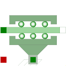
 Model Modelica.Mechanics.Translational.Components.Mass
Sliding mass with inertia, without friction and two rigidly connected flanges.
The sliding mass has the length L, the position coordinate s is in the middle. Sign convention: A positive force at flange flange_a moves the sliding mass in the positive direction. A negative force at flange flange_a moves the sliding mass to the negative direction.
Extends from Modelica.Mechanics.Translational.Interfaces.PartialRigid (Rigid connection of two translational 1D flanges).
| Type | Name | Default | Description |
|---|---|---|---|
Mass | m | Mass of the sliding mass | |
StateSelect | stateSelect | StateSelect.default | Priority to use s and v as states |
Length | L | 0 | Length of component, from left flange to right flange (= flange_b.s - flange_a.s) |
| Type | Name | Description |
|---|---|---|
Flange_a | flange_a | Left flange of translational component |
Flange_b | flange_b | Right flange of translational component |
 Model Modelica.Mechanics.Translational.Components.Rod
A translational rod without inertia and two rigidly connected flanges.
Extends from Modelica.Mechanics.Translational.Interfaces.PartialRigid (Rigid connection of two translational 1D flanges).
| Type | Name | Default | Description |
|---|---|---|---|
Length | L | Length of component, from left flange to right flange (= flange_b.s - flange_a.s) |
| Type | Name | Description |
|---|---|---|
Flange_a | flange_a | Left flange of translational component |
Flange_b | flange_b | Right flange of translational component |
 Model Modelica.Mechanics.Translational.Components.Spring
A linear 1D translational spring. The component can be connected either between two sliding masses, or between a sliding mass and the housing (model Fixed), to describe a coupling of the sliding mass with the housing via a spring.
Extends from Modelica.Mechanics.Translational.Interfaces.PartialCompliant (Compliant connection of two translational 1D flanges).
| Type | Name | Default | Description |
|---|---|---|---|
TranslationalSpringConstant | c | Spring constant | |
Distance | s_rel0 | 0 | Unstretched spring length |
| Type | Name | Description |
|---|---|---|
Flange_a | flange_a | Left flange of compliant 1-dim. translational component |
Flange_b | flange_b | Right flange of compliant 1-dim. translational component |
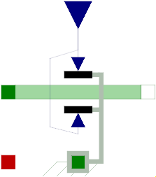
 Model Modelica.Mechanics.Translational.Components.Damper
Linear, velocity dependent damper element. It can be either connected between a sliding mass and the housing (model Fixed), or between two sliding masses.
Extends from Modelica.Mechanics.Translational.Interfaces.PartialCompliantWithRelativeStates (Base model for the compliant connection of two translational 1-dim. shaft flanges where the relative position and relative velocities are used as states) and Modelica.Thermal.HeatTransfer.Interfaces.PartialElementaryConditionalHeatPortWithoutT (Partial model to include a conditional HeatPort in order to dissipate losses, used for textual modeling, i.e., for elementary models).
| Type | Name | Default | Description |
|---|---|---|---|
StateSelect | stateSelect | StateSelect.prefer | Priority to use s_rel and v_rel as states |
Distance | s_nominal | 1e-4 | Nominal value of s_rel (used for scaling) |
TranslationalDampingConstant | d | Damping constant | |
Boolean | useHeatPort | false | =true, if heatPort is enabled |
| Type | Name | Description |
|---|---|---|
Flange_a | flange_a | Left flange of compliant 1-dim. translational component |
Flange_b | flange_b | Right flange of compliant 1-dim. translational component |
HeatPort_a | heatPort | Optional port to which dissipated losses are transported in form of heat |
 Model Modelica.Mechanics.Translational.Components.SpringDamper
A spring and damper element connected in parallel. The component can be connected either between two sliding masses to describe the elasticity and damping, or between a sliding mass and the housing (model Fixed), to describe a coupling of the sliding mass with the housing via a spring/damper.
Extends from Modelica.Mechanics.Translational.Interfaces.PartialCompliantWithRelativeStates (Base model for the compliant connection of two translational 1-dim. shaft flanges where the relative position and relative velocities are used as states) and Modelica.Thermal.HeatTransfer.Interfaces.PartialElementaryConditionalHeatPortWithoutT (Partial model to include a conditional HeatPort in order to dissipate losses, used for textual modeling, i.e., for elementary models).
| Type | Name | Default | Description |
|---|---|---|---|
StateSelect | stateSelect | StateSelect.prefer | Priority to use s_rel and v_rel as states |
Distance | s_nominal | 1e-4 | Nominal value of s_rel (used for scaling) |
TranslationalSpringConstant | c | Spring constant | |
TranslationalDampingConstant | d | Damping constant | |
Position | s_rel0 | 0 | Unstretched spring length |
Boolean | useHeatPort | false | =true, if heatPort is enabled |
| Type | Name | Description |
|---|---|---|
Flange_a | flange_a | Left flange of compliant 1-dim. translational component |
Flange_b | flange_b | Right flange of compliant 1-dim. translational component |
HeatPort_a | heatPort | Optional port to which dissipated losses are transported in form of heat |
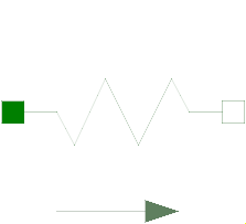
 Model Modelica.Mechanics.Translational.Components.ElastoGap
This component models a spring damper combination that can lift off. It can be connected between a sliding mass and the housing (model Fixed), to describe the contact of a sliding mass with the housing.
As long as s_rel > s_rel0, no force is exerted (s_rel = flange_b.s - flange_a.s). If s_rel ≤ s_rel0, the contact force is basically computed with a linear spring/damper characteristic. With parameter n≥1 (exponent of spring force), a nonlinear spring force can be modeled:
desiredContactForce = c*|s_rel - s_rel0|^n + d*der(s_rel)
Note, Hertzian contact is described by:
The above force law leads to the following difficulties:
In the literature there are several proposals to fix problem (2). Especially, often the following model is used (see, e.g., Lankarani, Nikravesh: Continuous Contact Force Models for Impact Analysis in Multibody Systems, Nonlinear Dynamics 5, pp. 193-207, 1994, pdf-download):
f = c*s_rel^n + (d*s_rel^n)*der(s_rel)
However, this and other models proposed in literature violate issue (1), i.e., unphysical pulling forces can occur (if d*der(s_rel) becomes large enough). Note, if the force law is of the form "f = f_c + f_d", then a necessary condition is that |f_d| ≤ |f_c|, otherwise (1) and (2) are violated. For this reason, the most simplest approach is used in the ElastoGap model to fix both problems by using this necessary condition in the force law directly. If s_rel0 = 0, the equations are:
    if s_rel ≥ 0 then
       f = 0;    // contact force
    else
       f_c  = -c*|s_rel|^n;          // contact spring force (Hertzian contact force)
       f_d2 = d*der(s_rel);         // linear contact damper force
       f_d  = if f_d2 <  f_c then  f_c else
              if f_d2 > -f_c then -f_c else f_d2;  // bounded damper force
       f    = f_c + f_d;            // contact force
    end if;
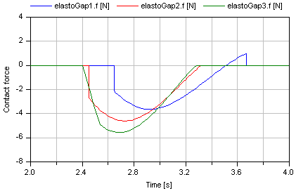
Note, since |f_d| ≤ |f_c|, pulling forces cannot occur and the contact force is always continuous, especially around the start of the penetration at s_rel = s_rel0.
In the next figure, a typical simulation with the ElastoGap model is shown (Examples.ElastoGap) where the different effects are visualized:
Extends from Modelica.Mechanics.Translational.Interfaces.PartialCompliantWithRelativeStates (Base model for the compliant connection of two translational 1-dim. shaft flanges where the relative position and relative velocities are used as states) and Modelica.Thermal.HeatTransfer.Interfaces.PartialElementaryConditionalHeatPortWithoutT (Partial model to include a conditional HeatPort in order to dissipate losses, used for textual modeling, i.e., for elementary models).
| Type | Name | Default | Description |
|---|---|---|---|
StateSelect | stateSelect | StateSelect.prefer | Priority to use s_rel and v_rel as states |
Distance | s_nominal | 1e-4 | Nominal value of s_rel (used for scaling) |
TranslationalSpringConstant | c | Spring constant | |
TranslationalDampingConstant | d | Damping constant | |
Position | s_rel0 | 0 | Unstretched spring length |
Real | n | 1 | Exponent of spring force ( f_c = -c*|s_rel-s_rel0|^n ) |
Boolean | useHeatPort | false | =true, if heatPort is enabled |
| Type | Name | Description |
|---|---|---|
Flange_a | flange_a | Left flange of compliant 1-dim. translational component |
Flange_b | flange_b | Right flange of compliant 1-dim. translational component |
HeatPort_a | heatPort | Optional port to which dissipated losses are transported in form of heat |
 Model Modelica.Mechanics.Translational.Components.SupportFriction
This element describes Coulomb friction in support, i.e., a frictional force acting between a flange and the housing. The positive sliding friction force "f" has to be defined by table "f_pos" as function of the absolute velocity "v". E.g.
       v |   f
      ---+-----
       0 |   0
       1 |   2
       2 |   5
       3 |   8
gives the following table:
f_pos = [0, 0; 1, 2; 2, 5; 3, 8];
Currently, only linear interpolation in the table is supported. Outside of the table, extrapolation through the last two table entries is used. It is assumed that the negative sliding friction force has the same characteristic with negative values. Friction is modelled in the following way:
When the absolute velocity "v" is not zero, the friction force is a function of v and of a constant normal force. This dependency is defined via table f_pos and can be determined by measurements, e.g., by driving the gear with constant velocity and measuring the needed driving force (= friction force).
When the absolute velocity becomes zero, the elements connected by the friction element become stuck, i.e., the absolute position remains constant. In this phase the friction force is calculated from a force balance due to the requirement, that the absolute acceleration shall be zero. The elements begin to slide when the friction force exceeds a threshold value, called the maximum static friction force, computed via:
maximum_static_friction = peak * sliding_friction(v=0) (peak >= 1)
This procedure is implemented in a "clean" way by state events and leads to continuous/discrete systems of equations if friction elements are dynamically coupled which have to be solved by appropriate numerical methods. The method is described in (see also a short sketch in UsersGuide.ModelingOfFriction):
More precise friction models take into account the elasticity of the material when the two elements are "stuck", as well as other effects, like hysteresis. This has the advantage that the friction element can be completely described by a differential equation without events. The drawback is that the system becomes stiff (about 10-20 times slower simulation) and that more material constants have to be supplied which requires more sophisticated identification. For more details, see the following references, especially (Armstrong and Canudas de Wit 1996):
Extends from Modelica.Mechanics.Translational.Interfaces.PartialElementaryTwoFlangesAndSupport2 (Partial model for a component with one translational 1-dim. shaft flange and a support used for textual modeling, i.e., for elementary models), Modelica.Thermal.HeatTransfer.Interfaces.PartialElementaryConditionalHeatPortWithoutT (Partial model to include a conditional HeatPort in order to dissipate losses, used for textual modeling, i.e., for elementary models), and Modelica.Mechanics.Translational.Interfaces.PartialFriction (Base model of Coulomb friction elements).
| Type | Name | Default | Description |
|---|---|---|---|
Boolean | useSupport | false | = true, if support flange enabled, otherwise implicitly grounded |
Boolean | useHeatPort | false | =true, if heatPort is enabled |
Real | f_pos[:,2] | [0,1] | [v, f] Positive sliding friction characteristic (v>=0) |
Real | peak | 1 | Peak for maximum friction force at w==0 (f0_max = peak*f_pos[1,2]) |
Velocity | v_small | 0.001 | Relative velocity near to zero (see model info text) |
| Type | Name | Description |
|---|---|---|
Flange_a | flange_a | Flange of left shaft |
Flange_b | flange_b | Flange of right shaft |
Support | support | Support/housing of component |
HeatPort_a | heatPort | Optional port to which dissipated losses are transported in form of heat |
 Model Modelica.Mechanics.Translational.Components.Brake
This component models a brake, i.e., a component where a frictional force is acting between the housing and a flange and a controlled normal force presses the flange to the housing in order to increase friction. The normal force fn has to be provided as input signal f_normalized in a normalized form (0 ≤ f_normalized ≤ 1), fn = fn_max*f_normalized, where fn_max has to be provided as parameter. Friction in the brake is modelled in the following way:
When the absolute velocity "v" is not zero, the friction force is a function of the velocity dependent friction coefficient mue(v) , of the normal force "fn", and of a geometry constant "cgeo" which takes into account the geometry of the device and the assumptions on the friction distributions:
frictional_force = cgeo * mue(v) * fn
Typical values of coefficients of friction:
      dry operation   :  mue = 0.2 .. 0.4
      operating in oil:  mue = 0.05 .. 0.1
The positive part of the friction characteristic mue(v), v >= 0, is defined via table mue_pos (first column = v, second column = mue). Currently, only linear interpolation in the table is supported.
When the absolute velocity becomes zero, the elements connected by the friction element become stuck, i.e., the absolute position remains constant. In this phase the friction force is calculated from a force balance due to the requirement, that the absolute acceleration shall be zero. The elements begin to slide when the friction force exceeds a threshold value, called the maximum static friction force, computed via:
frictional_force = peak * cgeo * mue(w=0) * fn (peak >= 1)
This procedure is implemented in a "clean" way by state events and leads to continuous/discrete systems of equations if friction elements are dynamically coupled. The method is described in:
More precise friction models take into account the elasticity of the material when the two elements are "stuck", as well as other effects, like hysteresis. This has the advantage that the friction element can be completely described by a differential equation without events. The drawback is that the system becomes stiff (about 10-20 times slower simulation) and that more material constants have to be supplied which requires more sophisticated identification. For more details, see the following references, especially (Armstrong and Canudas de Wit 1996):
Extends from Modelica.Mechanics.Translational.Interfaces.PartialElementaryTwoFlangesAndSupport2 (Partial model for a component with one translational 1-dim. shaft flange and a support used for textual modeling, i.e., for elementary models), Modelica.Thermal.HeatTransfer.Interfaces.PartialElementaryConditionalHeatPortWithoutT (Partial model to include a conditional HeatPort in order to dissipate losses, used for textual modeling, i.e., for elementary models), and Modelica.Mechanics.Translational.Interfaces.PartialFriction (Base model of Coulomb friction elements).
| Type | Name | Default | Description |
|---|---|---|---|
Boolean | useSupport | false | = true, if support flange enabled, otherwise implicitly grounded |
Boolean | useHeatPort | false | =true, if heatPort is enabled |
Real | mue_pos[:,2] | [0,0.5] | [v, f] Positive sliding friction characteristic (v>=0) |
Real | peak | 1 | Peak for maximum value of mue at w==0 (mue0_max = peak*mue_pos[1,2]) |
Real | cgeo | 1 | Geometry constant containing friction distribution assumption |
Force | fn_max | Maximum normal force | |
Velocity | v_small | 0.001 | Relative velocity near to zero (see model info text) |
| Type | Name | Description |
|---|---|---|
Flange_a | flange_a | Flange of left shaft |
Flange_b | flange_b | Flange of right shaft |
Support | support | Support/housing of component |
HeatPort_a | heatPort | Optional port to which dissipated losses are transported in form of heat |
input RealInput | f_normalized | Normalized force signal 0..1 (normal force = fn_max*f_normalized; brake is active if > 0) |
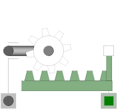 Model Modelica.Mechanics.Translational.Components.IdealGearR2T
Couples rotational and translational motion, like a toothed wheel with a toothed rack, specifying the ratio of rotational / translational motion.
Extends from Modelica.Mechanics.Rotational.Components.IdealGearR2T (Gearbox transforming rotational into translational motion).
| Type | Name | Default | Description |
|---|---|---|---|
Boolean | useSupportR | false | = true, if rotational support flange enabled, otherwise implicitly grounded |
Boolean | useSupportT | false | = true, if translational support flange enabled, otherwise implicitly grounded |
Real | ratio | Transmission ratio (flange_a.phi/flange_b.s) |
| Type | Name | Description |
|---|---|---|
Flange_a | flangeR | Flange of rotational shaft |
Flange_b | flangeT | Flange of translational rod |
Support | supportR | Rotational support/housing of component |
Support | supportT | Translational support/housing of component |
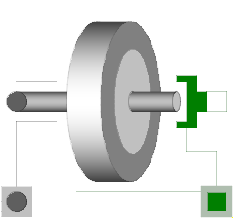 Model Modelica.Mechanics.Translational.Components.IdealRollingWheel
Couples rotational and translational motion, like an ideal rolling wheel, specifying the wheel radius.
Extends from Modelica.Mechanics.Rotational.Components.IdealRollingWheel (Simple 1-dim. model of an ideal rolling wheel without inertia).
| Type | Name | Default | Description |
|---|---|---|---|
Boolean | useSupportR | false | = true, if rotational support flange enabled, otherwise implicitly grounded |
Boolean | useSupportT | false | = true, if translational support flange enabled, otherwise implicitly grounded |
Distance | radius | Wheel radius |
| Type | Name | Description |
|---|---|---|
Flange_a | flangeR | Flange of rotational shaft |
Flange_b | flangeT | Flange of translational rod |
Support | supportR | Rotational support/housing of component |
Support | supportT | Translational support/housing of component |
 Model Modelica.Mechanics.Translational.Components.InitializeFlange
This component is used to optionally initialize the position, speed, and/or acceleration of the flange to which this component is connected. Via parameters use_s_start, use_v_start, use_a_start the corresponding input signals s_start, v_start, a_start are conditionally activated. If an input is activated, the corresponding flange property is initialized with the input value at start time.
For example, if "use_s_start = true", then flange.s is initialized with the value of the input signal "s_start" at the start time.
Additionally, it is optionally possible to define the "StateSelect" attribute of the flange position and the flange speed via parameter "stateSelection".
This component is especially useful when the initial values of a flange shall be set according to reference signals of a controller that are provided via a signal bus.
Extends from Modelica.Blocks.Icons.Block (Basic graphical layout of input/output block).
| Type | Name | Default | Description |
|---|---|---|---|
Boolean | use_s_start | true | = true, if initial position is defined by input s_start, otherwise not initialized |
Boolean | use_v_start | true | = true, if initial speed is defined by input v_start, otherwise not initialized |
Boolean | use_a_start | true | = true, if initial acceleration is defined by input a_start, otherwise not initialized |
StateSelect | stateSelect | StateSelect.default | Priority to use flange angle and speed as states |
| Type | Name | Description |
|---|---|---|
input RealInput | s_start | Initial position of flange |
input RealInput | v_start | Initial speed of flange |
input RealInput | a_start | Initial angular acceleration of flange |
Flange_b | flange | Flange that is initialized |
 Model Modelica.Mechanics.Translational.Components.MassWithStopAndFriction
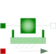
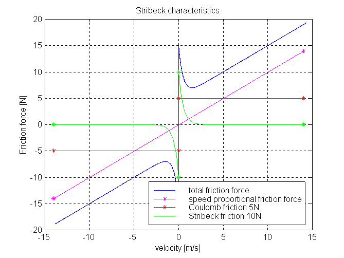
This element describes the Stribeck friction characteristics of a sliding mass, i. e. the frictional force acting between the sliding mass and the support. Included is a hard stop for the position.
The surface is fixed and there is friction between sliding mass and surface. The frictional force f is given for positive velocity v by:
f = F_Coulomb + F_prop * v + F_Stribeck * exp (-fexp * v)
The distance between the left and the right connector is given by parameter L. The position of the center of gravity, coordinate s, is in the middle between the two flanges.
There are hard stops at smax and smin, i. e. if
flange_a.s >= smin and flange_b.s <= xmax the sliding mass can move freely.
When the absolute velocity becomes zero, the sliding mass becomes stuck, i.e., the absolute position remains constant. In this phase the friction force is calculated from a force balance due to the requirement that the absolute acceleration shall be zero. The elements begin to slide when the friction force exceeds a threshold value, called the maximum static friction force, computed via:
maximum_static_friction = F_Coulomb + F_Stribeck
This requires the states Stop.s and Stop.v . If these states are eliminated during the index reduction the model will not work. To avoid this any inertias should be connected via springs to the Stop element, other sliding masses, dampers or hydraulic chambers must be avoided.
For more details of the used friction model see the following reference:
The friction model is implemented in a "clean" way by state events and leads to continuous/discrete systems of equations which have to be solved by appropriate numerical methods. The method is described in (see also a short sketch in UsersGuide.ModelingOfFriction):
More precise friction models take into account the elasticity of the material when the two elements are "stuck", as well as other effects, like hysteresis. This has the advantage that the friction element can be completely described by a differential equation without events. The drawback is that the system becomes stiff (about 10-20 times slower simulation) and that more material constants have to be supplied which requires more sophisticated identification. For more details, see the following references, especially (Armstrong and Canudas de Wit 1996):
The dissipated energy is transported in form of heat to the optional heatPort connector that can be enabled via parameter "useHeatPort". Independently whether the heatPort is or is not enabled, the dissipated power is defined with variable "lossPower". If contact occurs at the hard stops, the lossPower is not correctly modelled at this time instant, because the hard stop would introduce a Dirac impulse in the lossPower due to the discontinuously changing kinetic energy of the mass (lossPower is the derivative of the kinetic energy at the time instant of the impact).
Extends from Modelica.Mechanics.Translational.Components.MassWithStopAndFriction.PartialFrictionWithStop (Base model of Coulomb friction elements with stop) and Modelica.Thermal.HeatTransfer.Interfaces.PartialElementaryConditionalHeatPortWithoutT (Partial model to include a conditional HeatPort in order to dissipate losses, used for textual modeling, i.e., for elementary models).
| Type | Name | Default | Description |
|---|---|---|---|
Position | smax | Right stop for (right end of) sliding mass | |
Position | smin | Left stop for (left end of) sliding mass | |
Velocity | v_small | 0.001 | Relative velocity near to zero (see model info text) |
Length | L | Length of component, from left flange to right flange (= flange_b.s - flange_a.s) | |
Mass | m | Mass | |
Real | F_prop | Velocity dependent friction | |
Force | F_Coulomb | Constant friction: Coulomb force | |
Force | F_Stribeck | Stribeck effect | |
Real | fexp | Exponential decay | |
Boolean | useHeatPort | false | =true, if heatPort is enabled |
| Type | Name | Description |
|---|---|---|
Flange_a | flange_a | Left flange of translational component |
Flange_b | flange_b | Right flange of translational component |
HeatPort_a | heatPort | Optional port to which dissipated losses are transported in form of heat |
 Model Modelica.Mechanics.Translational.Components.RelativeStates
Usually, the absolute position and the absolute velocity of Modelica.Mechanics.Translational.Inertia models are used as state variables. In some circumstances, relative quantities are better suited, e.g., because it may be easier to supply initial values. In such cases, model RelativeStates allows the definition of state variables in the following way:
An example is given in the next figure
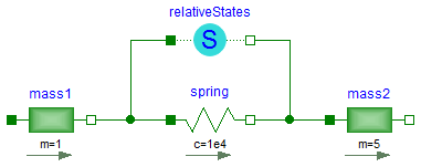
Here, the relative position and the relative velocity between the two masses are used as state variables. Additionally, the simulator selects either the absolute position and absolute velocity of model mass1 or of model mass2 as state variables.
Extends from Modelica.Mechanics.Translational.Interfaces.PartialTwoFlanges (Component with two translational 1D flanges).
| Type | Name | Default | Description |
|---|---|---|---|
StateSelect | stateSelect | StateSelect.prefer | Priority to use the relative angle and relative speed as states |
| Type | Name | Description |
|---|---|---|
Flange_a | flange_a | (left) driving flange (flange axis directed in to cut plane, e. g. from left to right) |
Flange_b | flange_b | (right) driven flange (flange axis directed out of cut plane) |
 Model Modelica.Mechanics.Translational.Components.GeneralForceToPositionAdaptor
Adaptor between a flange connector and a signal representation of the flange. This component is used to provide a pure signal interface around a Translational model and export this model in form of an input/output block, especially as FMU (Functional Mock-up Unit). Examples of the usage of this adaptor are provided in Translational.Examples.GenerationOfFMUs. This adaptor has force as input and position, velocity and acceleration as output signals.
Extends from Modelica.Blocks.Interfaces.Adaptors.FlowToPotentialAdaptor (Signal adaptor for a connector with flow, 1st derivative of flow, and 2nd derivative of flow as inputs and
potential, 1st derivative of potential, and 2nd derivative of potential as outputs (especially useful for FMUs)).
| Type | Name | Default | Description |
|---|---|---|---|
Boolean | use_pder | true | Use output for 1st derivative of potential |
Boolean | use_pder2 | true | Use output for 2nd derivative of potential (only if 1st derivate is used, too) |
final Boolean | use_fder | false | Use input for 1st derivative of flow |
final Boolean | use_fder2 | false | Use input for 2nd derivative of flow (only if 1st derivate is used, too) |
| Type | Name | Description |
|---|---|---|
output RealOutput | p | Output for potential |
output RealOutput | pder | Optional output for der(potential) |
output RealOutput | pder2 | Optional output for der2(potential) |
input RealInput | f | Input for flow |
input RealInput | fder | Optional input for der(flow) |
input RealInput | fder2 | Optional input for der2(flow) |
Flange_a | flange |
 Model Modelica.Mechanics.Translational.Components.GeneralPositionToForceAdaptor
Adaptor between a flange connector and a signal representation of the flange. This component is used to provide a pure signal interface around a Translational model and export this model in form of an input/output block, especially as FMU (Functional Mock-up Unit). Examples of the usage of this adaptor are provided in Translational.Examples.GenerationOfFMUs. This adaptor has position, velocity and acceleration as input signals and force as output signal.
Note, the input signals must be consistent to each other (v=der(s), a=der(v)).
Extends from Modelica.Blocks.Interfaces.Adaptors.PotentialToFlowAdaptor (Signal adaptor for a connector with potential, 1st derivative of potential, and 2nd derivative of potential as inputs and
flow, 1st derivative of flow, and 2nd derivative of flow as outputs (especially useful for FMUs)).
| Type | Name | Default | Description |
|---|---|---|---|
Boolean | use_pder | true | Use input for 1st derivative of potential |
Boolean | use_pder2 | true | Use input for 2nd derivative of potential (only if 1st derivate is used, too) |
final Boolean | use_fder | false | Use output for 1st derivative of flow |
final Boolean | use_fder2 | false | Use output for 2nd derivative of flow (only if 1st derivate is used, too) |
| Type | Name | Description |
|---|---|---|
input RealInput | p | Input for potential |
input RealInput | pder | Optional input for der(potential) |
input RealInput | pder2 | Optional input for der2(potential) |
output RealOutput | f | Output for flow |
output RealOutput | fder | Optional output for der(flow) |
output RealOutput | fder2 | Optional output for der2(flow) |
Flange_b | flange |