Set Simulation Parameters

Before executing a simulation, you can define parameters for simulation time, zero-crossing and solvers.
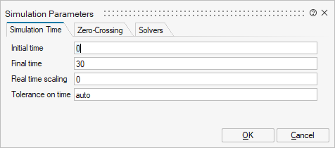
On the ribbon, select the simulation Setup tool:
The Simulation Parameters dialog appears:

Set Simulation Time

Define the time parameters for your simulation requirements.

On the Simulation Parameters dialog, select the Simulation Time tab. Define the options as required for your simulation:
For parameter Do this
Initial time Enter a value to start the simulation.
Final time Enter a value to end the simulation.
Tip: You can also define Final Time by adding an End block to your diagram. The End block includes a parameterized simulation time.
Real time scaling Enter a value to scale and insert a delay into the simulation time. For example, if you enter 0 (zero), the real time is ignored and the simulation runs as fast as possible; if you enter 1, one unit of the simulation time = 1 second; if you enter 10, one unit = 10 seconds.
Tolerence on time Enter a value to define the acceptable error between event times. The value for the tolerance on time lets the Simulator ignore the very small time differences between event times.
This is an advanced parameter that lets you compare two time quantities and detect for example:
  • When the difference between the simulator time and an event is less than the tolerance threshold.
  • Two time events that are very close together. For example, if the difference between the instants of several time events is less than the time-tolerance, the time events are considered to be simultaneous.
  • A zero-crossing, in which case the software stops the iteration when the difference between the time instants of the right- and left-hand sides of the zero-crossing is less than the tolerance threshold.

The tolerance-on-time value is computed dynamically as a function of the current simulation time and the machine’s epsilon. If this value is very low or very high, simulation problems can occur. Changing the value depends on the model and requested error tolerance. Generally, if you choose a loose error tolerance, the zero-crossing surfaces need not be precisely detected. If the value is set to auto, and the simulation fails, enter a low value such as 1e-14, and then gradually increase the value as required.

Set Zero Crossing

Define this advanced parameter to handle discontinuities or generate events.

  1. On the Simulation Parameters dialog, select the Zero Crossing tab.
  2. Define the options for the zero-crossing threshold and time tolerance as required for your simulation.
    Parameter Description
    Zero-crossing threshold The zero-crossing detection mechanism has a threshold to avoid chattering or repeated zero crossings during a model simulation. When detected, the zero crossing is considered as zero until the absolute value of crossed surfaces becomes greater than the zero-crossing threshold. The value of the zero-crossing threshold can be user-defined or computed dynamically by the simulator using the partial derivatives of the zero-crossing surfaces.
    Zero-crossing time tolerance The option stops the zero-crossing detection when the difference between the left- and right-hand side of the zero crossing becomes less than this threshold. If the Tolerance on Time option on the Simulation Time tab is set to auto, the global time threshold is applied.

    For more information about the zero-crossing parameter, see the chapter, Altair Activate Hybrid Simulator and Interface with Numerical Solvers in the Extended Definitions.

Specify a Solver

Choose a solver and define solver parameters for your simulation requirements.

For information about Solvers, see the chapter, Altair Activate Hybrid Simulator and Interface with Numerical Solvers in the Extended Definitions.
On the Simulation Parameters dialog, select the Solvers tab and define the options in the tab as required for your simulation.
Tip: You can monitor the solver step-size with the SimulatorInfo block found in the Activate > ActivationOperations palette.