ACU-T: 3600 Melting of Diesel Exhaust Additive within an Enclosed Tank
This tutorial provides the directions for setting up, solving, and post-processing results for a simulation that models the approximated melting of the common diesel fuel exhaust additive that is contained within a notional tank. Prior to starting this tutorial, you should have already run through the introductory HyperWorks tutorial, ACU-T: 1000 HyperWorks UI Introduction, and have a basic understanding of HyperWorks CFD and AcuSolve. To run this simulation, you will need access to a licensed version of HyperWorks CFD and AcuSolve.
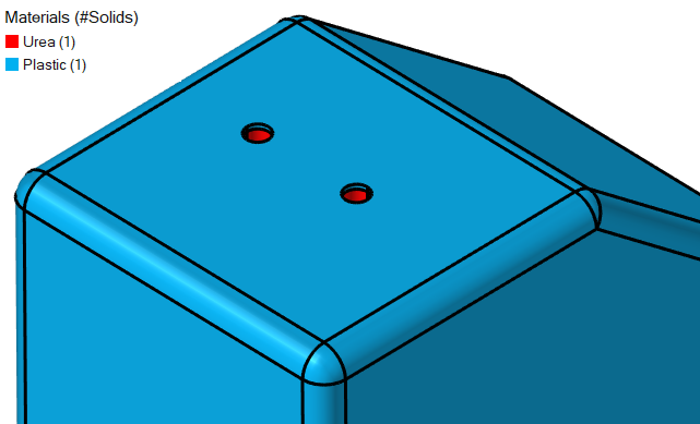
Problem Description
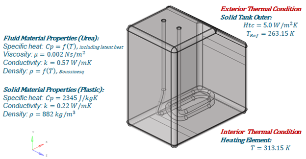
Figure 1.
Start HyperWorks CFD and Open the HyperMesh Database
Validate the Geometry
The Validate tool scans through the entire model, performs checks on the surfaces and solids, and flags any defects in the geometry, such as free edges, closed shells, intersections, duplicates, and slivers.

Figure 3.
Set Up Flow
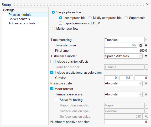
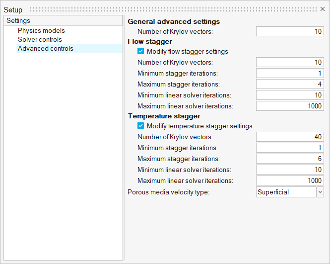
Set Up the Simulation Parameters and Solver Settings
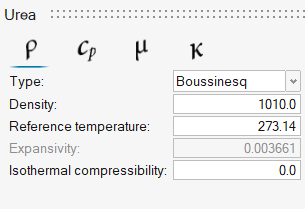
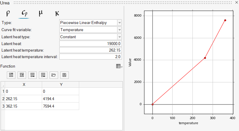
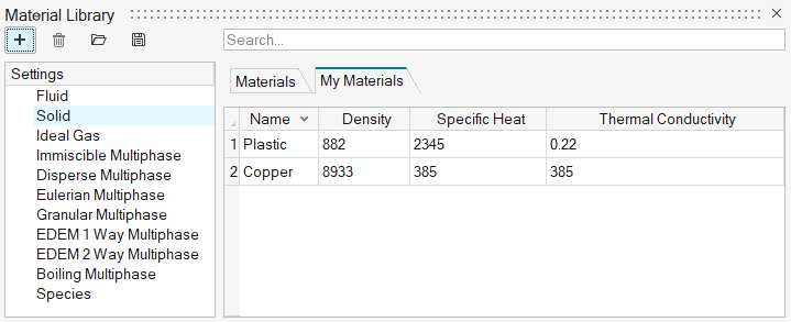
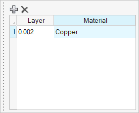
Assign Material Properties
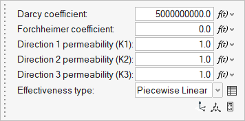
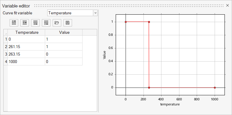
Define the Porous Medium
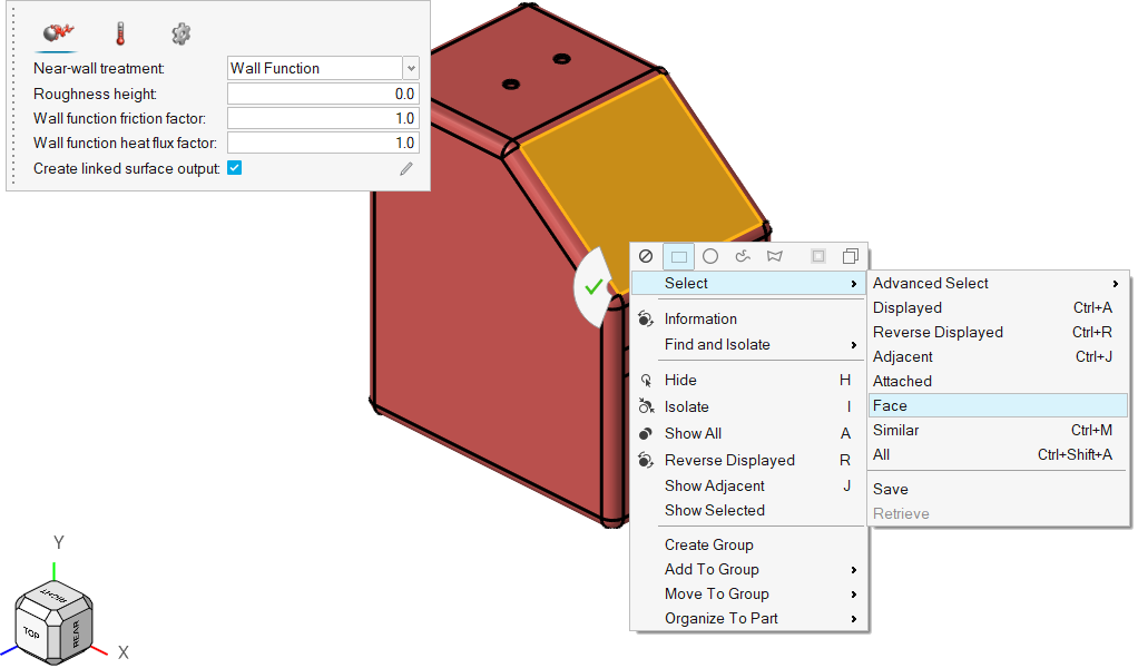
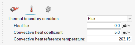
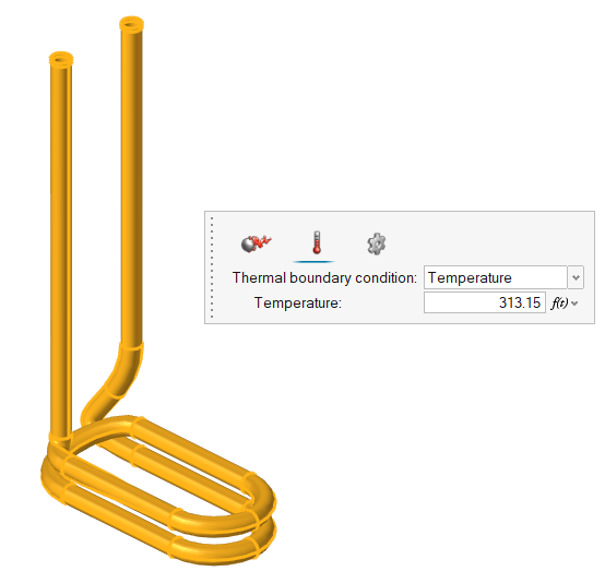
Assign the Flow Boundary Conditions
Generate the Mesh
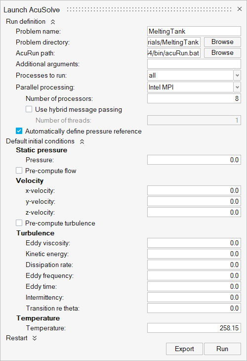
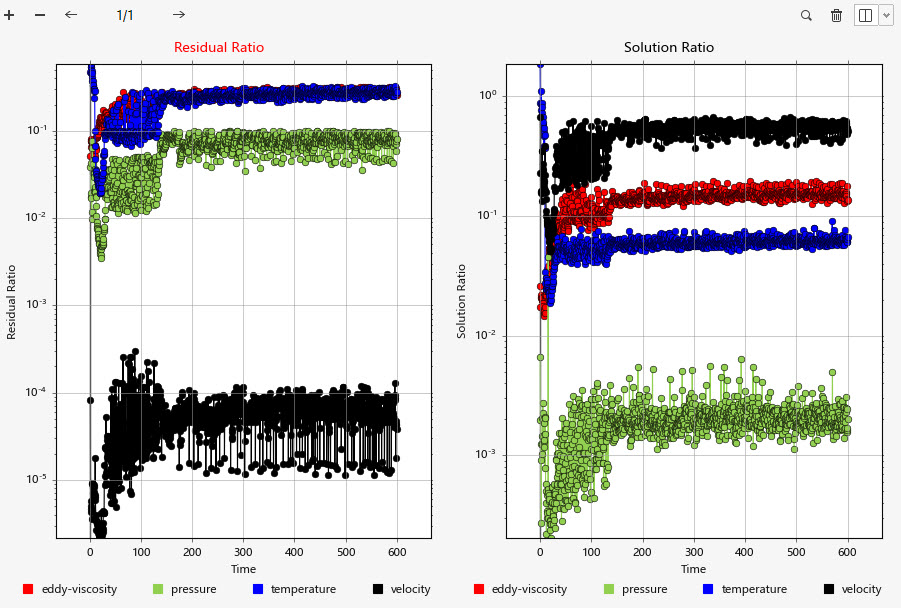
Define a Surface Monitor and Run AcuSolve
Post-Process the Results
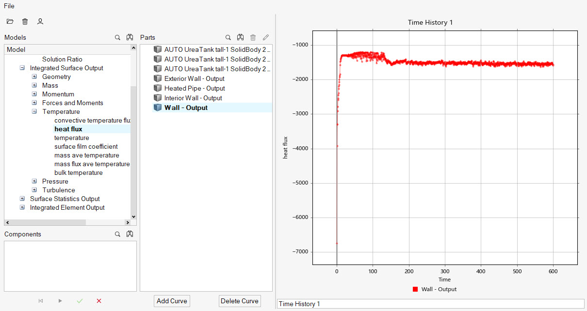
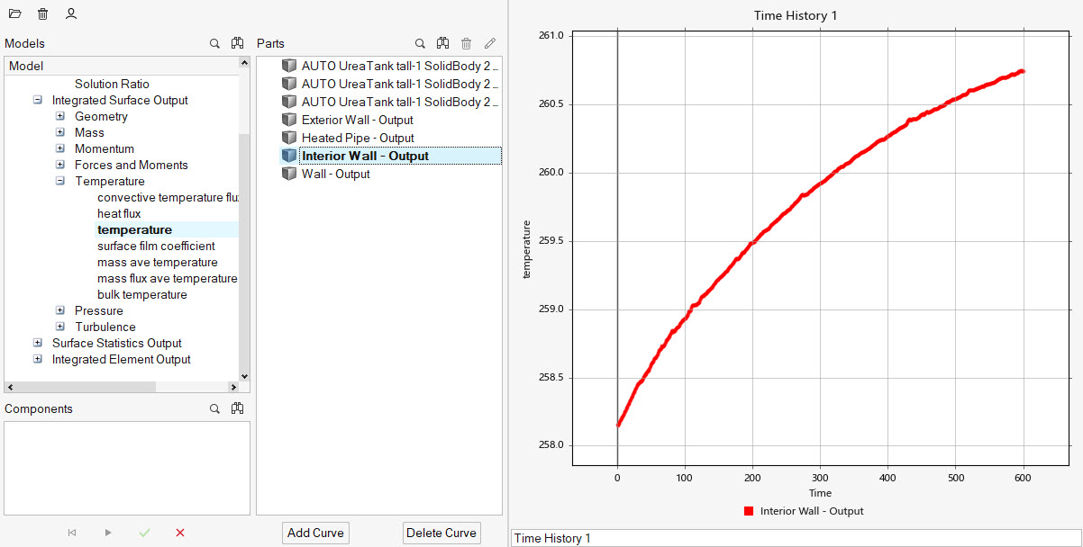
Post-Process with the Plot Tool
Post-Process with HyperWorks CFD Post
Summary
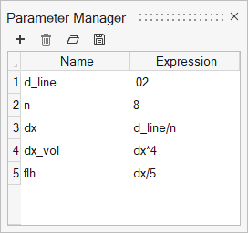
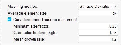
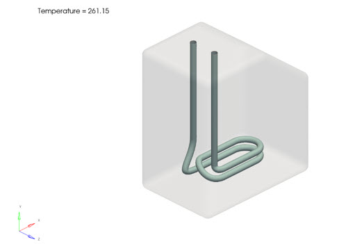
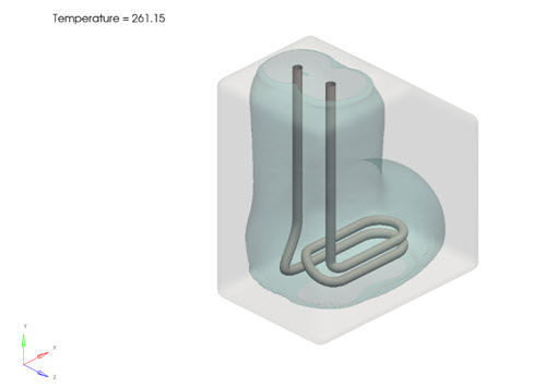
In this tutorial, you learned how to set up and solve a flow and thermal simulation with temperature dependent porous media effectiveness. Utilizing the proposed implementation allowed you to specify the melting point of a fluid and compute the melted region of the fluid. You started by importing the HyperWorks CFD input database and then you defined the porous medium to control the melting point of the fluid. Next, you assigned the thermal boundary conditions and generated the mesh using the parametric variable definitions. Once the solution was computed, you created a plot of the heat flux and temperature for the critical surfaces with the model using HyperWorks CFD Plot Manager.


