ACU-T: 6100 Particle Separation in a Windshifter using Altair EDEM
This tutorial introduces you to the workflow for setting up and running a basic sequential coupling (one-way steady) simulation using AcuSolve and EDEM. Prior to starting this tutorial, you should have already run through the introductory HyperWorks tutorial, ACU-T: 1000 HyperWorks UI Introduction, and have a basic understanding of HyperWorks CFD, AcuSolve, and EDEM. To run this simulation, you will need access to a licensed version of HyperWorks CFD, AcuSolve, and EDEM.
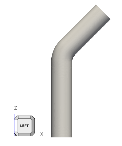
Problem Description
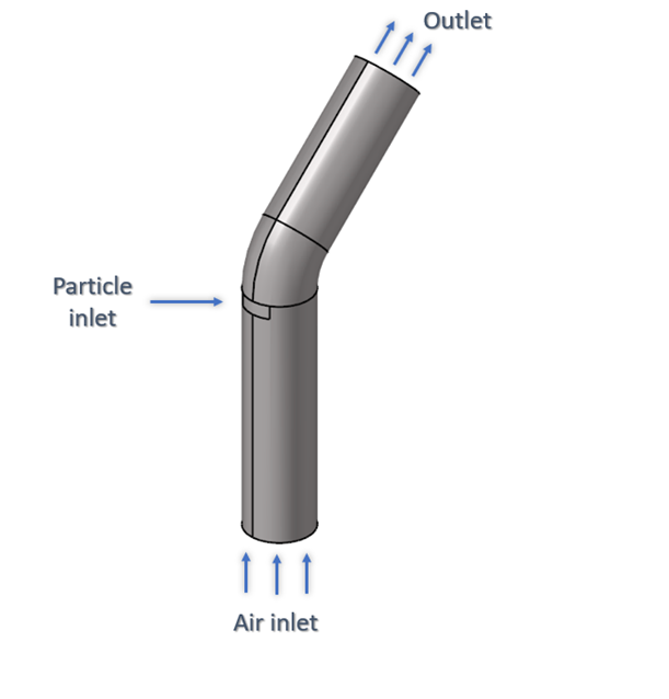
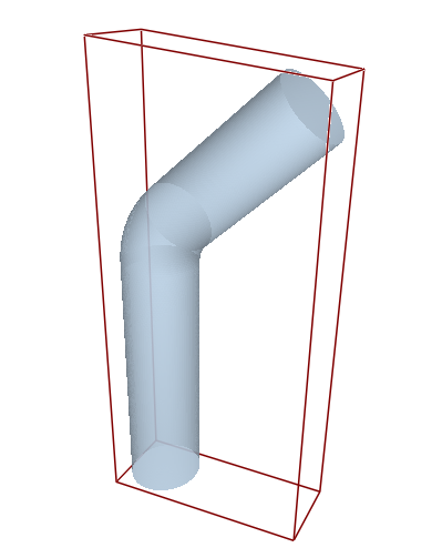
Figure 1.
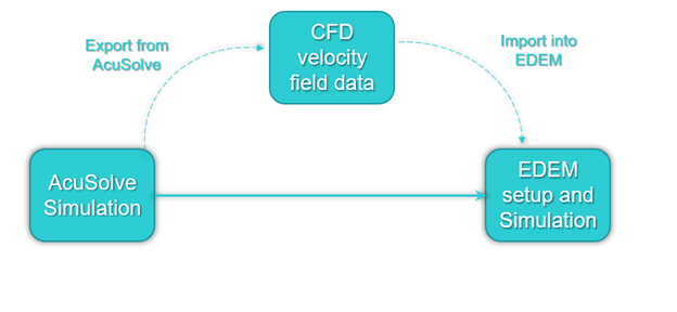
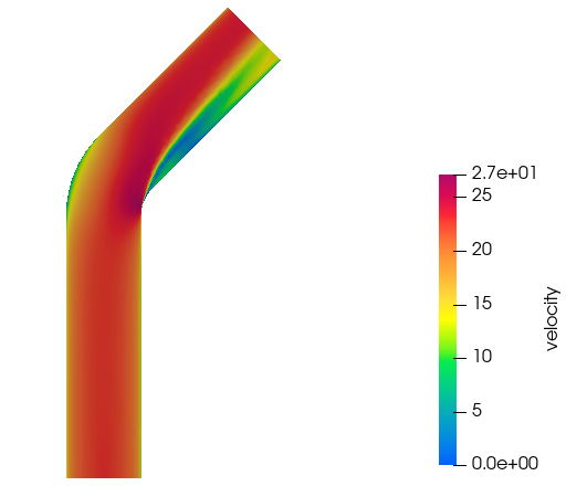
Figure 2.
The tutorial consists of two parts:
- AcuSolve simulation
- EDEM simulation
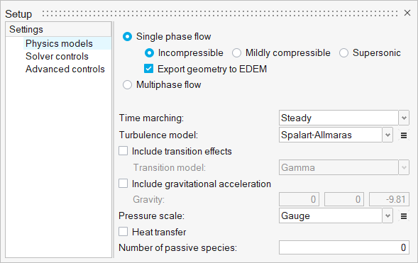
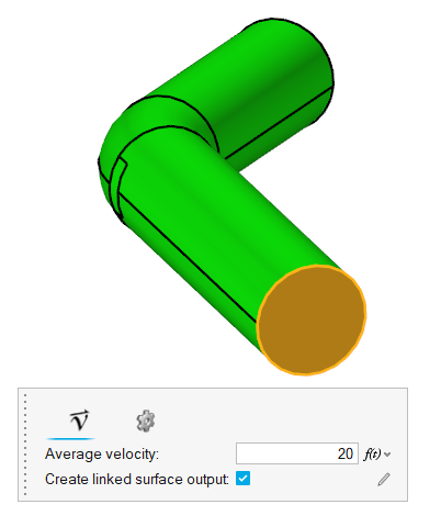
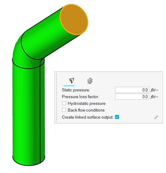
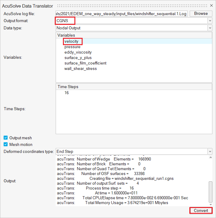
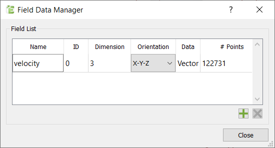
The setup for the AcuSolve simulation is done using HyperWorks CFD. Once the AcuSolve simulation is complete, the velocity nodal data is exported into CGNS format using the AcuTrans utility available in AcuSolve. This field data will be imported into EDEM and will be used to calculate the drag forces on the particles due to the fluid.
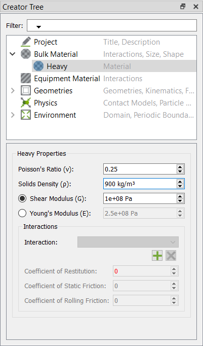
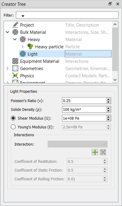
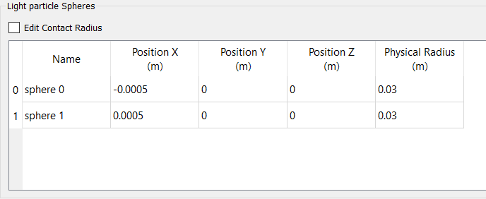
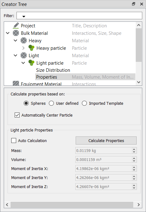
Two different bulk materials used in the EDEM simulation and their properties are listed below:
| Name | Density (kg/m3) | Particle radius (m) | Average weight of individual particle (kg) | Rate of generation (particles per sec) |
|---|---|---|---|---|
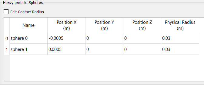
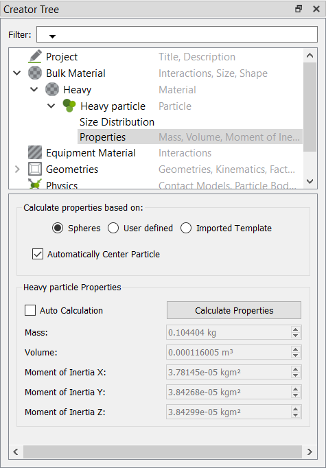
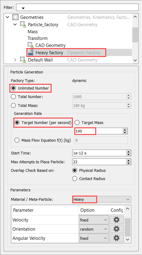
| Heavy particle | 900 | 0.03 | 0.004 | 100 |
| Light particle | 100 | 0.03 | 0.0004 | 100 |
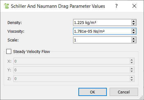
The fluid drag forces on the particles are calculated using the Schiller-Naumann drag model. The drag force on the particle is calculated using the relative velocity of the particle with respect to the local fluid velocity. This particle body force will used to update the location of the particles and then the new drag forces are calculated. This loop is repeated until the end of the simulation.
Part 1 - AcuSolve Simulation
Start HyperWorks CFD and Open the HyperMesh Database
Validate the Geometry
The Validate tool scans through the entire model, performs checks on the surfaces and solids, and flags any defects in the geometry, such as free edges, closed shells, intersections, duplicates, and slivers.

Figure 4.
Set Up Flow
Set the General Simulation Parameters
Assign Material Properties
Define Flow Boundary Conditions
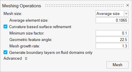
Generate the Mesh
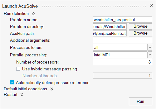
Run AcuSolve
Export Velocity Field Data
Post-Process the Results with HW-CFD Post
Part 2 - EDEM Simulation
Start Altair EDEM from the Windows start menu by clicking . The user interface in EDEM is divided into three tabs: Creator, Simulator and Analyst. The Creator is used to setup and initialize your model. It is where you import particles and geometries and define the other model parameters. The Simulator is where you configure and control the EDEM simulation engine, and where you can observe the progress of your simulation. The Analyst is the post-processor used to analyze and visualize the results of your simulation.
The steps required to setup and run a basic CFD-DEM one-way coupling are explained below. Please refer to the EDEM help documentation for more details.
Open the EDEM Input Deck
As mentioned earlier, when the AcuSolve simulation was launched, HyperWorks CFD created a set of EDEM files in the problem directory. You will open that EDEM input deck and setup the DEM simulation
Define the Bulk Materials and Equipment Material
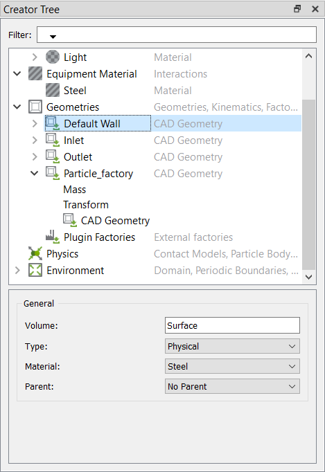
In this step, you will define the material models for the heavy and light bulk material and the equipment material.
Create the Particle Factory
Define the Particle Factory
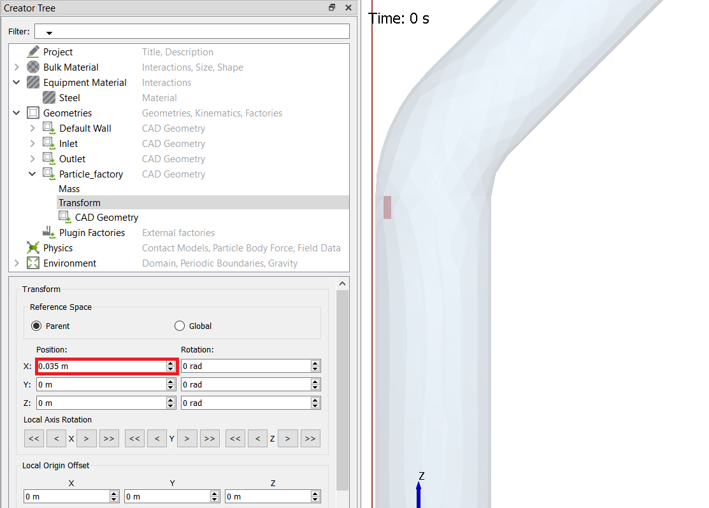
Now that the bulk material, geometry sections, and equipment materials are defined, you need to create a particle factory to generate the particles. You will create one factory for each bulk material.
Define the Physics and Import CFD Field Data
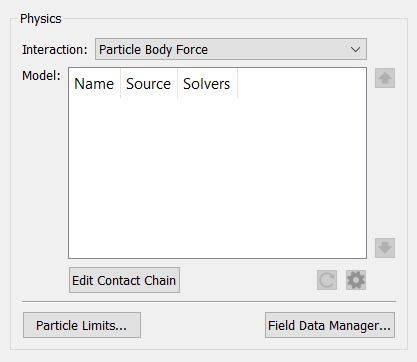
In this step, you will define the physics models for particle collisions and the particle body force.
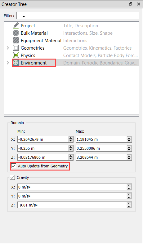
Define the Environment
In this step, you will define the extents of the domain for the EDEM simulation and the direction of gravitational acceleration.
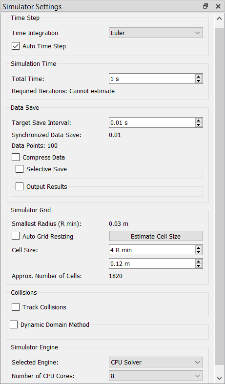
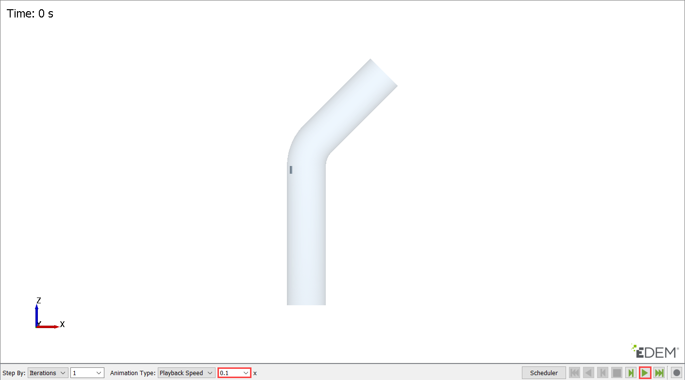
Define the Simulation Settings and Run the Simulation
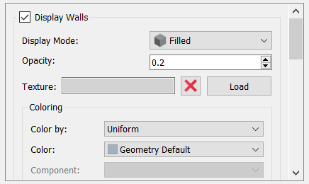
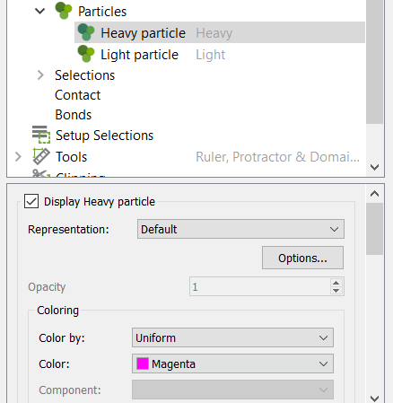
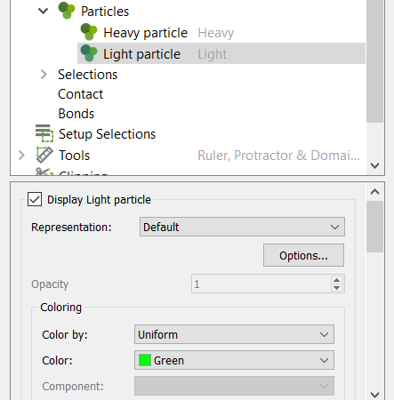
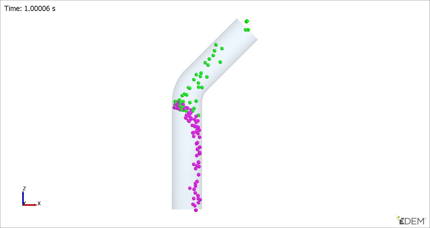
Analyze the Results
Summary
In tutorial you learned how to setup a basic AcuSolve-EDEM sequential (one-way steady) coupling problem. In the first part, you set up and solved a steady state flow simulation using AcuSolve and then exported the CFD field data using AcuTrans. Next, you set up the EDEM model and imported the CFD field data using the Field Data Manager. Once the EDEM simulation was completed, you learned how to view results and create animations in EDEM Analyst.


