ACU-T: 3300 Modeling of a Heat Exchanger Component
Prerequisites
This tutorial provides instructions for running a steady-state simulation of a flow inside a pipe with an interior heat exchanger placed at the middle of the pipe. Prior to starting this tutorial, you should have already run through the introductory tutorial, ACU-T: 1000 HyperWorks UI Introduction, and have a basic understanding of HyperMesh and AcuSolve. To run this simulation, you will need access to a licensed version of HyperMesh and AcuSolve.
Since the HyperMesh database (.hm file) contains meshed geometry, this tutorial does not include steps related to geometry import and mesh generation.
Problem Description
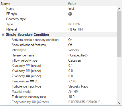
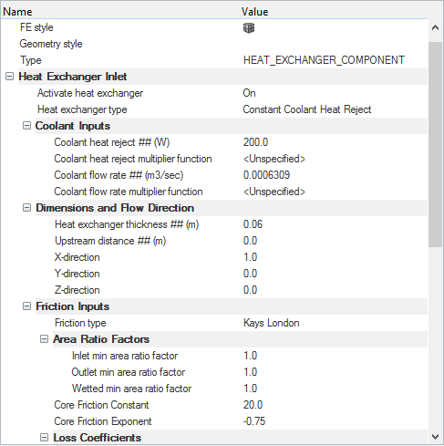
The problem to be addressed in this tutorial is shown schematically in the figure below. It consists of a cylindrical pipe channel with an interior heat exchanger component volume with thickness ‘t’ and radius ‘r’. The heat exchanger component parameters are assigned to the HEX_Inlet surface component. Basically, the heat exchanger model is applied to a surface and the temperature rises across that surface to model the effect of the heat exchanger. Air enters the pipe at a velocity of 0.1 m/sec and flows through the heat exchanger volume and then exits through the outlet.
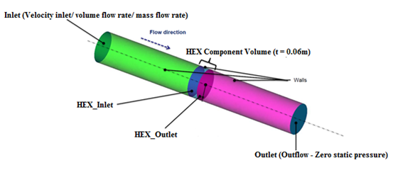
Figure 1.
Open the HyperMesh Model Database
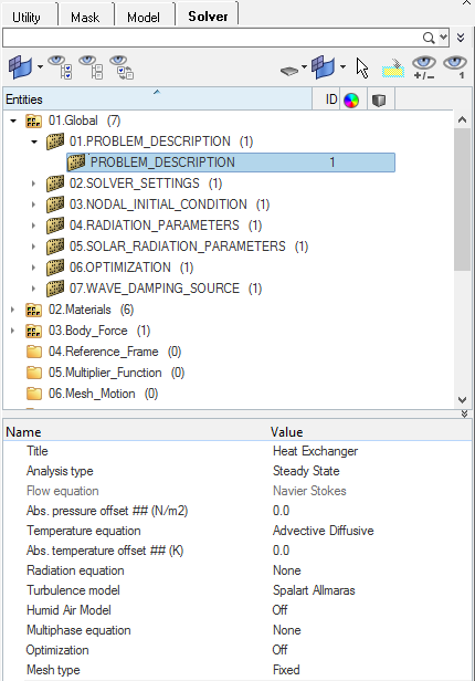
Set the General Simulation Parameters
In this step, you will set the simulation parameters that apply globally to the simulation.
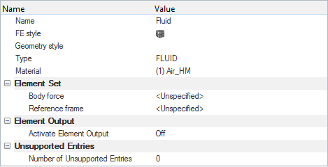
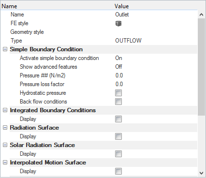
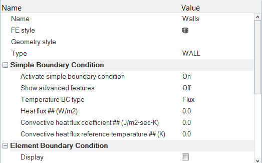
Set Up Boundary Conditions and Assign Material Model Parameters
Compute the Solution
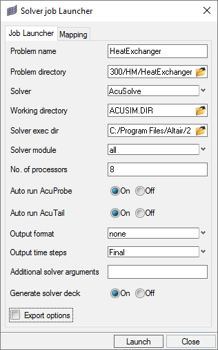
In this step, you will launch AcuSolve directly from HyperMesh and compute the solution.
Run AcuSolve
Post-Process with AcuProbe
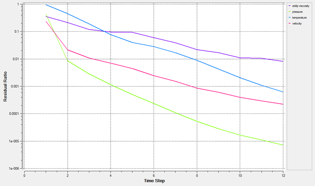
As the solution progresses, the AcuTail and AcuProbe windows are launched automatically. The surface output and residual ratios can be monitored using AcuProbe.
Summary
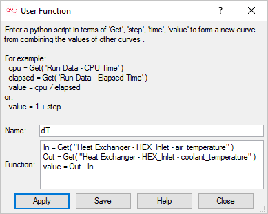
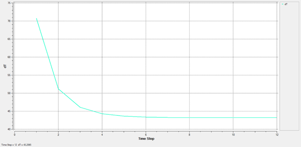
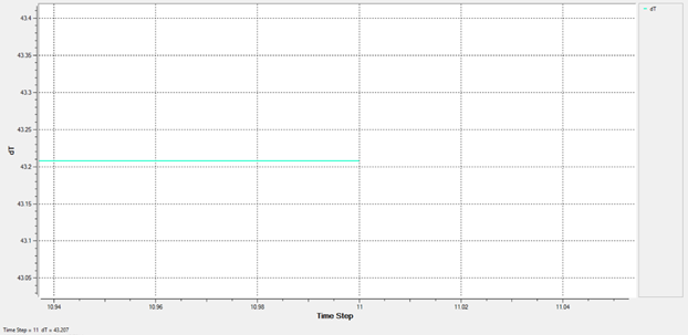
In this tutorial, you successfully learned how to set up and solve a simulation involving a Heat Exchanger component. You imported the meshed geometry and then assigned the boundary conditions and material properties for all the regions. Once the solution was computed, you defined a user function in AcuProbe in order to create a plot of the temperature rise across the heat exchanger volume.
