HM-4850: Introduction to Samcef

In this step you will: define the hypothesis on the elements; create isotropic materials, shell properties, and loads and load cases; assign properties and materials to elements; and export the model.

Before you begin, copy the hook.hm from <hm.zip>/interfaces/samcef/ to your working directory.

Load the Samcef User Profile

In this step, you will load the Samcef profile in HyperMesh.

  1. Start HyperMesh Desktop.
  2. In the User Profiles dialog, set the user profile to Samcef.

Retrieve and View the Model File

In this step, you will retrieve and view the model file in HyperMesh.

  1. Open a model file by completing one of the following options:
    • Click File > Open > Model from the menu bar.
    • Click on the Standard toolbar.
  2. In the Open Model dialog, open the hook.hm file.
  3. On the Visualization toolbar, click to shade the models elements and mesh lines, if they are not already shaded.
    The model appears in the graphics area.


    Figure 1.

Check the Hypothesis

In this step, you will check the Samcef hypothesis using the 2D & 3D subpanel.

  1. Open the Element Types panel by clicking Mesh > Assign > Element Type from the menu bar.
  2. Go to the 2D & 3D subpanel.
    In this panel, you have the link between the keyword of HyperMesh (tria3, quad4, ...) and the hypothesis of Samcef. You can change the hypothesis for each element configuration and also update each element with a different hypothesis.


    Figure 2.
  3. Click return to close the panel.

Create a Material

In this step, you will create a new material named steel.

  1. In the Model Browser, right-click and select Create > Material from the context menu.


    Figure 3.
    A new material opens in the Entity Editor.
  2. Define the material properties in the Entity Editor.
    1. For Name, enter steel.
    2. Set card image to ISOTROPIC.
      Note: You can create different types of elastic material (anisotropic, isotropic or orthotropic).
    3. Select a color for the material.
  3. In the Model Browser, Property folder, right-click on steel and select Card Edit from thecontext menu.
    The card image opens.
  4. Define the properties in the card image.
    1. For YT, enter 2.1e5.
    2. For NT, enter 0.3.
    3. For M, enter 7.9e-9.


    Figure 4.
  5. Click return to exit the card image.

Create and Assign Properties

In this step, you will create the properties and assign them to the elements.

  1. In the Model Browser, right-click and select Create > Property from the context menu.


    Figure 5.
    A new property opens in the Entity Editor.
  2. Define the property properties in the Entity Editor.
    1. For Name, enter shell.
    2. Set card image to SHELLPHP.
    3. Select a color for the property.
    4. For Material, click Unspecified > Material.
    5. In the Select Material dialog, select steel and then click OK.


      Figure 6.
  3. In the Model Browser, Property folder, right-click on shell and select Card Edit from thecontext menu.
  4. Define settings in the card image.
    1. In the card image, select the THICK checkbox.
    2. In the THICK field, enter 1.5.


      Figure 7.
    3. Click return to close the card image.
  5. In the Model Browser, Component folder, right-click on shell and select Assign from the context menu.
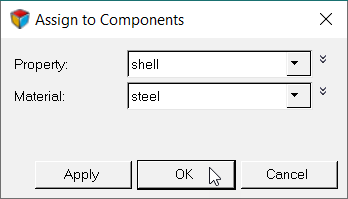
  6. Define settings in the Assign to Components dialog.
    1. Set Property to shell.
    2. Set Material to steel.
    3. Click OK.


      Figure 8.
      The property is now assigned to the elements.
  7. Repeat step 1.
  8. Define the property settings in the Entity Editor.
    1. For name, enter solid.
    2. Set card image to SOLIDMAT.
  9. In the Model Browser, Component folder, right-click on solid and select Assign from the context menu.
  10. Define settings in the Assign to Components dialog.
    1. Set Property to solid.
    2. Set Material to steel.
    3. Click OK.
      The property is now assigned to the elements.
  11. Ensure the properties are correctly assigned to the elements by clicking .
    The elements should have the same color as the properties.


    Figure 9.

Create Load Collectors

In this step, you will create two load collectors named spc and force.

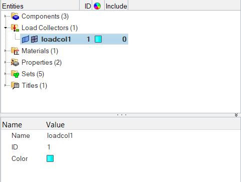
  1. In the Model Browser, right-click and select Create > Load Collector from the context menu.


    Figure 10.
    A new load collector opens in the Entity Editor.
  2. Define the load collector properties in the Entity Editor.
    1. For Name, enter spc.
    2. Select a color for the load collector.
  3. Repeat step 1.
  4. Define the load collector properties in the Entity Editor.
    1. For Name, enter force.
    2. Select a color for the load collector.

Create Constraints

In this step, you will create constraints.

  1. In the Model Browser, Load Collectors folder, right-click on spc and select Make Current from the context menu.
    This sets the spc load collector as the current load collector.
  2. Open the Constraints panel by clicking BCs > Create > Constraints from the menu bar.
  3. Go to the create subpanel.
  4. Using the nodes selector, select the main nodes of the rigid elements.
    Tip: The main nodes of the rigid elements are defined in the holes of the component solid.


    Figure 11.
  5. Constrain dof1, dof2, dof3, dof4, dof5, and dof6 by checking the corresponding checkboxes.
  6. Set dof1, dof2, dof3, dof4, dof5 and dof6 to a value of 0.0.
    DOFs with a check will be constrained, while DOFs without a check will be free. DOFs 1, 2 and 3 are x, y, and z translational degrees of freedom. DOFs 4, 5 and 6 are x, y an z rotational degrees of freedom.


    Figure 12.
  7. Click create to apply the constraints to the selected nodes.
  8. Click return to close the panel.

Create Forces

In this step, you will create forces.

  1. In the Model Browser, Load Collector folder, right-click on force and select Make Current from the context menu.
    This sets the force load collector as the current load collector.
  2. Open the Forces panel by clicking BCs > Create > Forces from the menu bar.
  3. Go to the create subpanel.
  4. Using the nodes selector, select the main nodes of the rigid element as seen in Figure 13.


    Figure 13.
  5. Set the local system / global system toggle to global system.
  6. Set the vector definition switch to constant vector.
  7. In the magnitude = field, enter 250.
  8. Set the orientation selector to z-axis.


    Figure 14.
  9. Click create.
  10. Click return.

Create a Samcef Database

In this step, you will create a Samcef database using the Load Steps panel.

  1. Open the Load Steps panel by clicking Setup > Create > Load Steps from the menu bar.
  2. In the name field, enter z-force.
  3. Using the loadcols selector, select the force and spc load collectors.
  4. Click create.
  5. Click return to close the panel.

Export the File

In this step, you will export the file.

  1. From the menu bar, click File > Export > Solver Deck.
    The Export - Solver Deck tab opens.
  2. In the File field, enter hook.dat.
  3. Set template to Samcef.
  4. Click Export.