Spotweld (Bolt or Adhesive Connection)

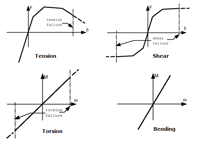
There are three different ways of modeling spotwelds:
  • Nodal connection
  • Spring (/PROP/TYPE13) connection
  • Solid connection

Spring (/PROP/TYPE13) connection and solid connection may also be used to model a bolted or adhesive connection (glue).

Nodal Connection

A single interface TYPE2 with the first surface as the main side and some nodes from the second surface as secondary nodes: With this solution the mesh of the main surface can be independent of the spotweld location. Hourglass problems disappear on the main surface. On the second shell, the surface mesh must respect the spotweld location and the hourglass problem will remain. The main problem with this modeling approach is the undeformability of the connection and its infinite strength.


Figure 1. Example of Connection between 2 Shell Surfaces

Spring (/PROP/TYPE13) Connection
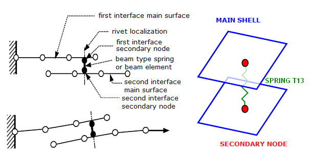
Two tied interfaces and a spring: The use of two tied interfaces will provide a full symmetrical solution allowing a free mesh on the two surfaces and avoiding hourglass. The spotweld is modeled with a beam type spring element. The spring element uses independent nodes not connected directed to the shell elements. One of the two nodes is located on the first surface (or near to it, there is no need to be located exactly on the shell surface) and the second node is located on the second surface. One tied interface connects one spring node with the first surface and a second tied interface does the same for the second node on the second surface.


Figure 2. Spotweld Modeling
To create a spotweld using this method is a good alternative solution with this approach the connection location is independent from the shell mesh. It is more accurate than the above node connection modeling, since the spotweld properties are input directly for the spring TYPE13.


Figure 3. Spring TYPE13 - Typical Input for Spotweld
Moreover, there are two different ways to model rupture of the spotweld:
  1. Use failure criteria which are available for a spring TYPE13. For more details, see the comments for failure criteria in /PROP/TYPE13 (SPR_BEAM).
  2. Use Spotflag= 20, 21, or 22 in the Tied Contact (Tied Contact (/INTER/TYPE2)).
    Note: The spring TYPE13 modeling technique for spotwelds can also be used for other kinds of connections such as welding lines, hemming, glue and bolts. For bolt modeling, the use of a tied interface is not necessary, as the shell nodes can be put directly in the rigid bodies.
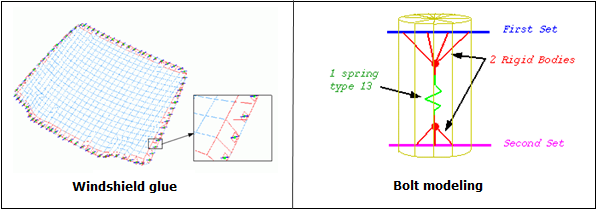

Figure 4. Glue and Bolt Modeling Examples
Note: With a tied interface, the secondary node mass is transferred to the main nodes, if Spotflag is set to 1. The secondary node inertia is equally distributed over the main nodes by adding mass, so that the induced inertia (at the center of the main surface) is equal to the inertia of the secondary node. If the main surface is a perfect square, the added mass is computed as:
l s = 4 Δ m L 2 MathType@MTEF@5@5@+= feaagKart1ev2aqatCvAUfeBSjuyZL2yd9gzLbvyNv2CaerbuLwBLn hiov2DGi1BTfMBaeXatLxBI9gBaerbd9wDYLwzYbItLDharqqtubsr 4rNCHbGeaGqiVu0Je9sqqrpepC0xbbL8F4rqqrFfpeea0xe9Lq=Jc9 vqaqpepm0xbba9pwe9Q8fs0=yqaqpepae9pg0FirpepeKkFr0xfr=x fr=xb9adbaqaaeGaciGaaiaabeqaamaabaabaaGcbaGaamiBamaaBa aaleaacaWGZbaabeaakiabg2da9iaaisdacqqHuoarcaWGTbGaeyyX ICTaamitamaaCaaaleqabaGaaGOmaaaaaaa@4036@
Δ m MathType@MTEF@5@5@+= feaagKart1ev2aqatCvAUfeBSjuyZL2yd9gzLbvyNv2CaerbuLwBLn hiov2DGi1BTfMBaeXatLxBI9gBaerbd9wDYLwzYbItLDharqqtubsr 4rNCHbGeaGqiVu0Je9sqqrpepC0xbbL8F4rqqrFfpeea0xe9Lq=Jc9 vqaqpepm0xbba9pwe9Q8fs0=yqaqpepae9pg0FirpepeKkFr0xfr=x fr=xb9adbaqaaeGaciGaaiaabeqaamaabaabaaGcbaGaeuiLdqKaam yBaaaa@384F@ : added mass
L: distance between the main node and the center
l s MathType@MTEF@5@5@+= feaagKart1ev2aaatCvAUfeBSjuyZL2yd9gzLbvyNv2CaerbuLwBLn hiov2DGi1BTfMBaeXatLxBI9gBaerbd9wDYLwzYbItLDharqqtubsr 4rNCHbGeaGqiVu0Je9sqqrpepC0xbbL8F4rqqrFfpeea0xe9Lq=Jc9 vqaqpepm0xbba9pwe9Q8fs0=yqaqpepae9pg0FirpepeKkFr0xfr=x fr=xb9adbaqaaeGaciGaaiaabeqaamaabaabaaGcbaGaamiBamaaBa aaleaacaWGZbaabeaaaaa@380B@ : inertia of the secondary node
As long as the secondary node inertia is realistic, the added mass will be very small. A large added mass is observed if the secondary node is too great a distance from the main surface. The ideal is for the secondary node to lie on the main surface plane, right at its center. If this is not the case, the secondary node has inertia at the center of the shell surface:
l s = m s L s 2 MathType@MTEF@5@5@+= feaagKart1ev2aqatCvAUfeBSjuyZL2yd9gzLbvyNv2CaerbuLwBLn hiov2DGi1BTfMBaeXatLxBI9gBaerbd9wDYLwzYbItLDharqqtubsr 4rNCHbGeaGqiVu0Je9sqqrpepC0xbbL8F4rqqrFfpeea0xe9Lq=Jc9 vqaqpepm0xbba9pwe9Q8fs0=yqaqpepae9pg0FirpepeKkFr0xfr=x fr=xb9adbaqaaeGaciGaaiaabeqaamaabaabaaGcbaGaamiBamaaBa aaleaacaWGZbaabeaakiabg2da9iaad2gadaWgaaWcbaGaam4Caaqa baGccqGHflY1caWGmbWaaSbaaSqaaiaadohaaeqaaOWaaWbaaSqabe aacaaIYaaaaaaa@406E@
m s MathType@MTEF@5@5@+= feaagKart1ev2aaatCvAUfeBSjuyZL2yd9gzLbvyNv2CaerbuLwBLn hiov2DGi1BTfMBaeXatLxBI9gBaerbd9wDYLwzYbItLDharqqtubsr 4rNCHbGeaGqiVu0Je9sqqrpepC0xbbL8F4rqqrFfpeea0xe9Lq=Jc9 vqaqpepm0xbba9pwe9Q8fs0=yqaqpepae9pg0FirpepeKkFr0xfr=x fr=xb9adbaqaaeGaciGaaiaabeqaamaabaabaaGcbaGaamiBamaaBa aaleaacaWGZbaabeaaaaa@380B@
Secondary node mass
L s MathType@MTEF@5@5@+= feaagKart1ev2aqatCvAUfeBSjuyZL2yd9gzLbvyNv2CaerbuLwBLn hiov2DGi1BTfMBaeXatLxBI9gBaerbd9wDYLwzYbItLDharqqtubsr 4rNCHbGeaGqiVu0Je9sqqrpepC0xbbL8F4rqqrFfpeea0xe9Lq=Jc9 vqaqpepm0xbba9pwe9Q8fs0=yqaqpepae9pg0FirpepeKkFr0xfr=x fr=xb9adbaqaaeGaciGaaiaabeqaamaabaabaaGcbaGaamitamaaBa aaleaacaWGZbaabeaaaaa@37EC@
Distance between the secondary node and the center
l s MathType@MTEF@5@5@+= feaagKart1ev2aaatCvAUfeBSjuyZL2yd9gzLbvyNv2CaerbuLwBLn hiov2DGi1BTfMBaeXatLxBI9gBaerbd9wDYLwzYbItLDharqqtubsr 4rNCHbGeaGqiVu0Je9sqqrpepC0xbbL8F4rqqrFfpeea0xe9Lq=Jc9 vqaqpepm0xbba9pwe9Q8fs0=yqaqpepae9pg0FirpepeKkFr0xfr=x fr=xb9adbaqaaeGaciGaaiaabeqaamaabaabaaGcbaGaamiBamaaBa aaleaacaWGZbaabeaaaaa@380B@
Inertia of the secondary node
Consequently, a new added mass is set to the main nodes, so that the inertia (due to this new added mass) is equal to the inertia, due to the off-centering of the secondary node.(1) 4 Δ m L 2 = m s L s 2 MathType@MTEF@5@5@+= feaagKart1ev2aqatCvAUfeBSjuyZL2yd9gzLbvyNv2CaerbuLwBLn hiov2DGi1BTfMBaeXatLxBI9gBaerbd9wDYLwzYbItLDharqqtubsr 4rNCHbGeaGqiVu0Je9sqqrpepC0xbbL8F4rqqrFfpeea0xe9Lq=Jc9 vqaqpepm0xbba9pwe9Q8fs0=yqaqpepae9pg0FirpepeKkFr0xfr=x fr=xb9adbaqaaeGaciGaaiaabeqaamaabaabaaGcbaGaaGinaiabfs 5aejaad2gacqGHflY1caWGmbWaaWbaaSqabeaacaaIYaaaaOGaeyyp a0JaamyBamaaBaaaleaacaWGZbaabeaakiabgwSixlaadYeadaWgaa WcbaGaam4CaaqabaGcdaahaaWcbeqaaiaaikdaaaaaaa@4573@

If Spotflag=0, there is no added mass, since the secondary node inertia instead is transferred as inertia to the main node. An added inertia that is too large will seriously decrease the accuracy.

Solid Spotweld

Uses 8-node brick element (with /PROP/TYPE43) and /MAT/LAW59+/FAIL/CONNECT (or /MAT/LAW83+/FAIL/SNCONNECT) to model solid spotwelds, which may provide more accurate results.

Solid Element and Property

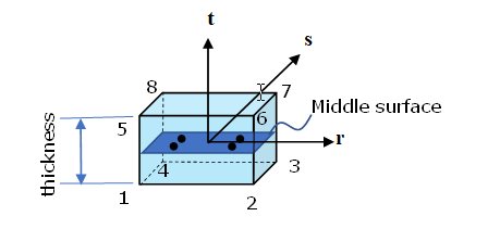
The brick element uses /PROP/TYPE43 and it has 4 integration points on the shear plane, which is between plane (1, 2, 3, 4) and plane (5, 6, 7, 8). There is one integration point in normal direction t. This element type does not have a time step itself and its stability is ensured by its nodal connections. This means that the thickness of spotweld can be very small. This characteristic is very useful for modeling glue.


Figure 5.


Figure 6.

Connected to Shell Sheet

/INTER/TYPE2 may be used to connect solid spotwelds with two (upper and lower) main surfaces. Nodes of plane (1,2,3,4) tied on one shell, and nodes of plane (5,6,7,8) tied on another shell. It is not allowed to have any other plane (for example, plane (1,4,8,5)) tied on a shell.

Material and Failure Model

Solid spotwelds in Radioss may be modeled with /MAT/LAW59+/FAIL/CONNECT (or /MAT/LAW83+/FAIL/SNCONNECT). This material model should be validated with four load cases of spotweld tests.
  • Shear test (angle of loading and spotweld upper surface is 0 degrees below named 0 degree test)
  • Normal tensile test (90 degree test),
  • Shear and normal combined test (for example, 30 degree test, 45 degree test or 90 degree test)
  • Moment test (peel test)

E-Modulus

The stiffness of the spotweld in different tests is different. In the normal test, it is lower than in the shear test, due to deformation of the upper and lower sheets. Therefore, normally the stiffness measured is taken from true stress versus displacement curve of the shear test.

/MAT/LAW59+/FAIL/CONNECT

  • Material yield curve:
    In LAW59, spotweld material yield curves in normal direction and in shear direction are requested. The yield curve (Y_fct_IDN) in normal direction may be determined from the normal tensile test (90 degree test) and the yield curve (Y_fct_IDT) in shear direction may be determined from the shear test (0 degree test).
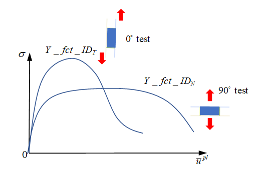

    Figure 7.

    In this case, the maximum stress is also described inside the curves. Given the reference displacement rate S R ref MathType@MTEF@5@5@+= feaagKart1ev2aqatCvAUfeBSjuyZL2yd9gzLbvyNv2CaerbuLwBLn hiov2DGi1BTfMBaeXatLxBI9gBaerbd9wDYLwzYbItLDharqqtubsr 4rNCHbGeaGqiVu0Je9sqqrpepC0xbbL8F4rqGqFfpeea0xe9vq=Jb9 vqpeea0xd9q8qiYRWxGi6xij=hbba9q8aq0=yq=He9q8qiLsFr0=vr 0=vr0db8meaabaqaciGacaGaaeqabaWaaeaaeaaakeaacaWGtbGaam OuamaaBaaaleaacaWGYbGaamyzaiaadAgaaeqaaaaa@3C0F@ of the input yield curve, Radioss will consider the displacement rate effect with respect to this reference displacement rate.

  • Spotweld failure:
    Solid spotweld damage and failure may be considered with /FAIL/CONNECT. Displacement criteria and/or energy criteria may be used to describe the failure of the spotweld.
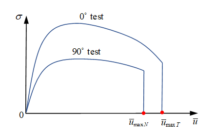
    • For displacement criteria, failure occurs when the normal displacement or shear displacement is reached according to 2 alternative behavior types:
      • Uncoupled failure (Ifail=0: uni-directional failure)(2) u ¯ i f ( u ¯ ˙ ) > u ¯ m a x i MathType@MTEF@5@5@+= feaagKart1ev2aaatCvAUfeBSjuyZL2yd9gzLbvyNv2CaerbuLwBLn hiov2DGi1BTfMBaeXatLxBI9gBaerbd9wDYLwzYbItLDharqqtubsr 4rNCHbGeaGqiVu0Je9sqqrpepC0xbbL8F4rqGqFfpeea0xe9vq=Jb9 vqpeea0xd9q8qiYRWxGi6xij=hbba9q8aq0=yq=He9q8qiLsFr0=vr 0=vr0db8meaabaqaciGacaGaaeqabaWaaeaaeaaakeaaceWG1bGbae badaWgaaWcbaGaamyAaaqabaGccqGHflY1ciGGMbGaciikaiqadwha gaqegaGaaiaacMcacqGH+aGpceWG1bGbaebadaWgaaWcbaGaaiyBai aacggacaGG4bGaaiyAaaqabaaaaa@454D@

        with i MathType@MTEF@5@5@+= feaagKart1ev2aaatCvAUfeBSjuyZL2yd9gzLbvyNv2CaerbuLwBLn hiov2DGi1BTfMBaeXatLxBI9gBaerbd9wDYLwzYbItLDharqqtubsr 4rNCHbGeaGqipu0Je9sqqrpepC0xbbL8F4rqqrFfpeea0xe9Lq=Jc9 vqaqpepm0xbba9pwe9Q8fs0=yqaqpepae9pg0FirpepeKkFr0xfr=x fr=xb9adbaqaaeGaciGaaiaabeqaamaabaabaaGcbaGaamyAaaaa@36C4@ = 33 for normal direction and i MathType@MTEF@5@5@+= feaagKart1ev2aaatCvAUfeBSjuyZL2yd9gzLbvyNv2CaerbuLwBLn hiov2DGi1BTfMBaeXatLxBI9gBaerbd9wDYLwzYbItLDharqqtubsr 4rNCHbGeaGqipu0Je9sqqrpepC0xbbL8F4rqqrFfpeea0xe9Lq=Jc9 vqaqpepm0xbba9pwe9Q8fs0=yqaqpepae9pg0FirpepeKkFr0xfr=x fr=xb9adbaqaaeGaciGaaiaabeqaamaabaabaaGcbaGaamyAaaaa@36C4@ = 13 or 23 for tangent directions.

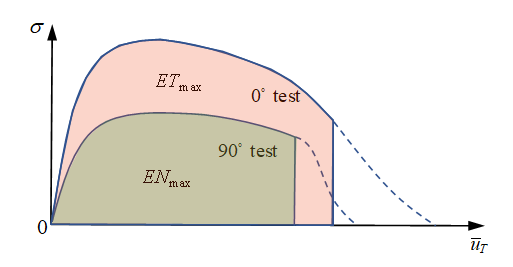
        In the normal tensile test (90 degree test), element fails once user-defined maximum displacement u ¯ max N MathType@MTEF@5@5@+= feaagKart1ev2aqatCvAUfeBSjuyZL2yd9gzLbvyNv2CaerbuLwBLn hiov2DGi1BTfMBaeXatLxBI9gBaerbd9wDYLwzYbItLDharqqtubsr 4rNCHbGeaGqiVu0Je9sqqrpepC0xbbL8F4rqGqFfpeea0xe9vq=Jb9 vqpeea0xd9q8qiYRWxGi6xij=hbba9q8aq0=yq=He9q8qiLsFr0=vr 0=vr0db8meaabaqaciGacaGaaeqabaWaaeaaeaaakeaaceWG1bGbae badaWgaaWcbaGaciyBaiaacggacaGG4bGaamOtaaqabaaaaa@3C4D@ is reached.

        In the shear tensile test (0 degree test), element fails once user-defined maximum displacement u ¯ max T MathType@MTEF@5@5@+= feaagKart1ev2aqatCvAUfeBSjuyZL2yd9gzLbvyNv2CaerbuLwBLn hiov2DGi1BTfMBaeXatLxBI9gBaerbd9wDYLwzYbItLDharqqtubsr 4rNCHbGeaGqiVu0Je9sqqrpepC0xbbL8F4rqGqFfpeea0xe9vq=Jb9 vqpeea0xd9q8qiYRWxGi6xij=hbba9q8aq0=yq=He9q8qiLsFr0=vr 0=vr0db8meaabaqaciGacaGaaeqabaWaaeaaeaaakeaaceWG1bGbae badaWgaaWcbaGaciyBaiaacggacaGG4bGaamivaaqabaaaaa@3C53@ is reached.


        Figure 8.

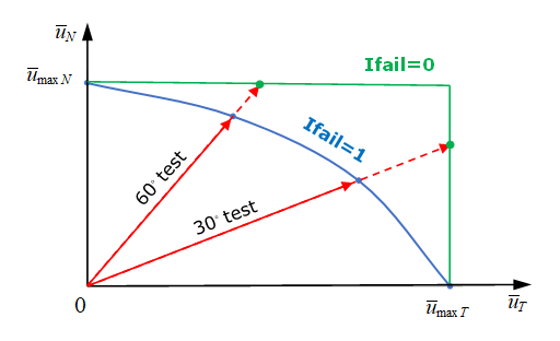
        In a combined mode test (for example, 30 degree test or 60 degree test), failure in the solid spotweld does not consider shear and normal combined stress effect. Failure in each direction is considered separately. The element fails as soon as either of these two stresses reaches its corresponding maximum displacement. To consider combined stresses, instead set Ifail=1 and combined stress effect will be then considered.

      • Coupled failure (Ifail=1: multi-directional failure)(3) | u ¯ N u ¯ max N α N f N ( u ¯ ˙ N ) | exp N + | u ¯ T u ¯ max T α T f T ( u ¯ ˙ T ) | exp T > 1 MathType@MTEF@5@5@+= feaagKart1ev2aaatCvAUfeBSjuyZL2yd9gzLbvyNv2CaerbuLwBLn hiov2DGi1BTfMBaeXatLxBI9gBaerbd9wDYLwzYbItLDharqqtubsr 4rNCHbGeaGqiVu0Je9sqqrpepC0xbbL8F4rqqrFfpeea0xe9Lq=Jc9 vqaqpepm0xbbG8FasPYRqj0=yi0dXdbba9pGe9xq=JbbG8A8frFve9 Fve9Ff0dmeaabaqaciGacaGaaeqabaWaaeaaeaaakeaadaabdiqaam aalaaabaGabmyDayaaraWaaSbaaSqaaiaad6eaaeqaaaGcbaGabmyD ayaaraWaaSbaaSqaaiGac2gacaGGHbGaaiiEaiaad6eaaeqaaaaaki abgwSixlabeg7aHnaaBaaaleaacaWGobaabeaakiabgwSixlGacAga daWgaaWcbaGaamOtaaqabaGcdaqadiqaaiqadwhagaqegaGaamaaBa aaleaacaWGobaabeaaaOGaayjkaiaawMcaaaGaay5bSlaawIa7amaa CaaaleqabaGaciyzaiaacIhacaGGWbWaaSbaaWqaaiaad6eaaeqaaa aakiaabUcadaabdiqaamaalaaabaGabmyDayaaraWaaSbaaSqaaiaa dsfaaeqaaaGcbaGabmyDayaaraWaaSbaaSqaaiGac2gacaGGHbGaai iEamaaBaaameaacaWGubaabeaaaSqabaaaaOGaeyyXICTaeqySde2a aSbaaSqaaiaadsfaaeqaaOGaeyyXICTaciOzamaaBaaaleaacaWGub aabeaakmaabmGabaGabmyDayaaryaacaWaaSbaaSqaaiaadsfaaeqa aaGccaGLOaGaayzkaaaacaGLhWUaayjcSdWaaWbaaSqabeaaciGGLb GaaiiEaiaacchadaWgaaadbaGaamivaaqabaaaaOGaeyOpa4JaaGym aaaa@6F89@

        With Ifail=1, in combined mode test, the element fails before reaching the maximum stress u ¯ max N MathType@MTEF@5@5@+= feaagKart1ev2aqatCvAUfeBSjuyZL2yd9gzLbvyNv2CaerbuLwBLn hiov2DGi1BTfMBaeXatLxBI9gBaerbd9wDYLwzYbItLDharqqtubsr 4rNCHbGeaGqiVu0Je9sqqrpepC0xbbL8F4rqGqFfpeea0xe9vq=Jb9 vqpeea0xd9q8qiYRWxGi6xij=hbba9q8aq0=yq=He9q8qiLsFr0=vr 0=vr0db8meaabaqaciGacaGaaeqabaWaaeaaeaaakeaaceWG1bGbae badaWgaaWcbaGaciyBaiaacggacaGG4bGaamOtaaqabaaaaa@3C4D@ or u ¯ max T MathType@MTEF@5@5@+= feaagKart1ev2aqatCvAUfeBSjuyZL2yd9gzLbvyNv2CaerbuLwBLn hiov2DGi1BTfMBaeXatLxBI9gBaerbd9wDYLwzYbItLDharqqtubsr 4rNCHbGeaGqiVu0Je9sqqrpepC0xbbL8F4rqGqFfpeea0xe9vq=Jb9 vqpeea0xd9q8qiYRWxGi6xij=hbba9q8aq0=yq=He9q8qiLsFr0=vr 0=vr0db8meaabaqaciGacaGaaeqabaWaaeaaeaaakeaaceWG1bGbae badaWgaaWcbaGaciyBaiaacggacaGG4bGaamivaaqabaaaaa@3C53@ which is closer to reality. To describe the curve failure surface you need at least 4 different combined tests to fit the parameters α N , α T , exp N , exp T MathType@MTEF@5@5@+= feaagKart1ev2aaatCvAUfeBSjuyZL2yd9gzLbvyNv2CaerbwvMCKf MBHbqefqvATv2CG4uz3bIuV1wyUbqedmvETj2BSbqefm0B1jxALjhi ov2DaebbnrfifHhDYfgasaacH8WjY=vipgYlh9vqqj=hEeeu0xXdbb a9frFj0=OqFfea0dXdd9vqai=hGuQ8kuc9pgc9q8qqaq=dir=f0=yq aiVgFr0xfr=xfr=xb9adbaGaaiGadiWaamaaceGaaqaacaqbaaGcba GaeqySde2aaSbaaSqaaiaad6eaaeqaaOGaaiilaiabeg7aHnaaBaaa leaacaWGubaabeaakiaacYcaciGGLbGaaiiEaiaacchadaWgaaWcba GaamOtaaqabaGccaGGSaGaciyzaiaacIhacaGGWbWaaSbaaSqaaiaa dsfaaeqaaaaa@47D6@ .


        Figure 9. Failure surface
    • For energy criteria, failure occurs when the internal energy in normal direction or internal energy in shear direction is reached, corresponding to maximum internal energy E N max , E T max MathType@MTEF@5@5@+= feaagKart1ev2aqatCvAUfeBSjuyZL2yd9gzLbvyNv2CaerbuLwBLn hiov2DGi1BTfMBaeXatLxBI9gBaerbd9wDYLwzYbItLDharqqtubsr 4rNCHbGeaGqiVu0Je9sqqrpepC0xbbL8F4rqGqFfpeea0xe9vq=Jb9 vqpeea0xd9q8qiYRWxGi6xij=hbba9q8aq0=yq=He9q8qiLsFr0=vr 0=vr0db8meaabaqaciGacaGaaeqabaWaaeaaeaaakeaacaWGfbGaam OtamaaBaaaleaaciGGTbGaaiyyaiaacIhaaeqaaOGaaiilaiaadwea caWGubWaaSbaaSqaaiGac2gacaGGHbGaaiiEaaqabaaaaa@4162@ .


      Figure 10.
      In a combined mode test, element failure is also considered with respect to the multi-direction effect on internal energy. If internal energy in normal direction and in shear direction are input, the element fails, if satisfied via:(4) ( E n E N max ) N n + ( E t E T max ) N t 1 MathType@MTEF@5@5@+= feaagKart1ev2aaatCvAUfeBSjuyZL2yd9gzLbvyNv2CaerbwvMCKf MBHbqefqvATv2CG4uz3bIuV1wyUbqedmvETj2BSbqefm0B1jxALjhi ov2DaebbnrfifHhDYfgasaacH8WjY=vipgYlh9vqqj=hEeeu0xXdbb a9frFj0=OqFfea0dXdd9vqai=hGuQ8kuc9pgc9q8qqaq=dir=f0=yq aiVgFr0xfr=xfr=xb9adbaGaaiGadiWaamaaceGaaqaacaqbaaGcba WaaeWaaeaadaWcaaqaaiaadweacaWGUbaabaGaamyraiaad6eadaWg aaWcbaGaciyBaiaacggacaGG4baabeaaaaaakiaawIcacaGLPaaada ahaaWcbeqaaiaad6eadaWgaaadbaGaamOBaaqabaaaaOGaey4kaSYa aeWaaeaadaWcaaqaaiaadweacaWG0baabaGaamyraiaadsfadaWgaa WcbaGaciyBaiaacggacaGG4baabeaaaaaakiaawIcacaGLPaaadaah aaWcbeqaaiaad6eadaWgaaadbaGaamiDaaqabaaaaOGaeyyzImRaaG ymaaaa@506F@
      To input only total internal energy E I max MathType@MTEF@5@5@+= feaagKart1ev2aqatCvAUfeBSjuyZL2yd9gzLbvyNv2CaerbuLwBLn hiov2DGi1BTfMBaeXatLxBI9gBaerbd9wDYLwzYbItLDharqqtubsr 4rNCHbGeaGqiVu0Je9sqqrpepC0xbbL8F4rqGqFfpeea0xe9vq=Jb9 vqpeea0xd9q8qiYRWxGi6xij=hbba9q8aq0=yq=He9q8qiLsFr0=vr 0=vr0db8meaabaqaciGacaGaaeqabaWaaeaaeaaakeaacaWGfbGaam ysamaaBaaaleaaciGGTbGaaiyyaiaacIhaaeqaaaaa@3C00@ , the element fails, if satisfied via:(5) E ( t ) E I max 1 MathType@MTEF@5@5@+= feaagKart1ev2aaatCvAUfeBSjuyZL2yd9gzLbvyNv2CaerbwvMCKf MBHbqefqvATv2CG4uz3bIuV1wyUbqedmvETj2BSbqefm0B1jxALjhi ov2DaebbnrfifHhDYfgasaacH8WjY=vipgYlh9vqqj=hEeeu0xXdbb a9frFj0=OqFfea0dXdd9vqai=hGuQ8kuc9pgc9q8qqaq=dir=f0=yq aiVgFr0xfr=xfr=xb9adbaGaaiGadiWaamaaceGaaqaacaqbaaGcba WaaSaaaeaacaWGfbGaaiikaiaadshacaGGPaaabaGaamyraiaadMea daWgaaWcbaGaciyBaiaacggacaGG4baabeaaaaGccqGHLjYScaaIXa aaaa@42FB@

      If both E I max MathType@MTEF@5@5@+= feaagKart1ev2aqatCvAUfeBSjuyZL2yd9gzLbvyNv2CaerbuLwBLn hiov2DGi1BTfMBaeXatLxBI9gBaerbd9wDYLwzYbItLDharqqtubsr 4rNCHbGeaGqiVu0Je9sqqrpepC0xbbL8F4rqGqFfpeea0xe9vq=Jb9 vqpeea0xd9q8qiYRWxGi6xij=hbba9q8aq0=yq=He9q8qiLsFr0=vr 0=vr0db8meaabaqaciGacaGaaeqabaWaaeaaeaaakeaacaWGfbGaam ysamaaBaaaleaaciGGTbGaaiyyaiaacIhaaeqaaaaa@3C00@ and E N max , E T max MathType@MTEF@5@5@+= feaagKart1ev2aqatCvAUfeBSjuyZL2yd9gzLbvyNv2CaerbuLwBLn hiov2DGi1BTfMBaeXatLxBI9gBaerbd9wDYLwzYbItLDharqqtubsr 4rNCHbGeaGqiVu0Je9sqqrpepC0xbbL8F4rqGqFfpeea0xe9vq=Jb9 vqpeea0xd9q8qiYRWxGi6xij=hbba9q8aq0=yq=He9q8qiLsFr0=vr 0=vr0db8meaabaqaciGacaGaaeqabaWaaeaaeaaakeaacaWGfbGaam OtamaaBaaaleaaciGGTbGaaiyyaiaacIhaaeqaaOGaaiilaiaadwea caWGubWaaSbaaSqaaiGac2gacaGGHbGaaiiEaaqabaaaaa@4162@ are input, the element fails, due to whichever of these two criteria is reached first.

      Both displacement criteria and energy criteria may be defined. The element fails, due to whichever criteria is reached first. The element deletion occurs when one integration point reaches the failure criteria, if Isolid=1 or when all integration points reach the failure criteria, if Isolid=2.

  • Spotweld softening:
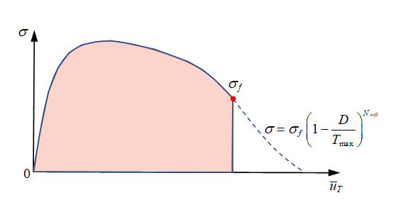
    After reaching the failure criteria (either displacement criteria or energy criteria) stress is reduced to 0 directly or may be gradually controlled with parameters T max MathType@MTEF@5@5@+= feaagKart1ev2aaatCvAUfeBSjuyZL2yd9gzLbvyNv2CaerbwvMCKf MBHbqefqvATv2CG4uz3bIuV1wyUbqedmvETj2BSbqefm0B1jxALjhi ov2DaebbnrfifHhDYfgasaacH8akY=xipgYlh9vqqj=hEeeu0xXdbb a9frFj0=OqFfea0dXdd9vqai=hGuQ8kuc9pgc9q8qqaq=dir=f0=yq aiVgFr0xfr=xfr=xb9adbaGaaiGadiWaamaaceGaaqaacaqbaaGcba GaamivamaaBaaaleaaciGGTbGaaiyyaiaacIhaaeqaaaaa@3CA6@ and N s o f t MathType@MTEF@5@5@+= feaagKart1ev2aqatCvAUfeBSjuyZL2yd9gzLbvyNv2CaerbuLwBLn hiov2DGi1BTfMBaeXatLxBI9gBaerbd9wDYLwzYbItLDharqqtubsr 4rNCHbGeaGqiVu0Je9sqqrpepC0xbbL8F4rqGqFfpeea0xe9vq=Jb9 vqpeea0xd9q8qiYRWxGi6xij=hbba9q8aq0=yq=He9q8qiLsFr0=vr 0=vr0db8meaabaqaciGacaGaaeqabaWaaeaaeaaakeaacaWGobWaaS baaSqaaiaadohacaWGVbGaamOzaiaadshaaeqaaaaa@3C37@ with:(6) σ = σ f ( 1 D T max ) N s o f t MathType@MTEF@5@5@+= feaagKart1ev2aaatCvAUfeBSjuyZL2yd9gzLbvyNv2CaerbwvMCKf MBHbqefqvATv2CG4uz3bIuV1wyUbqedmvETj2BSbqefm0B1jxALjhi ov2DaebbnrfifHhDYfgasaacH8akY=xipgYlh9vqqj=hEeeu0xXdbb a9frFj0=OqFfea0dXdd9vqai=hGuQ8kuc9pgc9q8qqaq=dir=f0=yq aiVgFr0xfr=xfr=xb9adbaGaaiGadiWaamaaceGaaqaacaqbaaGcba Gaeq4WdmNaeyypa0Jaeq4Wdm3aaSbaaSqaaiaadAgaaeqaaOWaaeWa ceaacaaIXaGaeyOeI0YaaSaaaeaacaWGebaabaGaamivamaaBaaale aaciGGTbGaaiyyaiaacIhaaeqaaaaaaOGaayjkaiaawMcaamaaCaaa leqabaGaamOtamaaBaaameaacaWGZbGaam4BaiaadAgacaWG0baabe aaaaaaaa@4B66@


    Figure 11.
    Figure 12 shows the effect of different T max MathType@MTEF@5@5@+= feaagKart1ev2aaatCvAUfeBSjuyZL2yd9gzLbvyNv2CaerbwvMCKf MBHbqefqvATv2CG4uz3bIuV1wyUbqedmvETj2BSbqefm0B1jxALjhi ov2DaebbnrfifHhDYfgasaacH8akY=xipgYlh9vqqj=hEeeu0xXdbb a9frFj0=OqFfea0dXdd9vqai=hGuQ8kuc9pgc9q8qqaq=dir=f0=yq aiVgFr0xfr=xfr=xb9adbaGaaiGadiWaamaaceGaaqaacaqbaaGcba GaamivamaaBaaaleaaciGGTbGaaiyyaiaacIhaaeqaaaaa@3CA6@ and N s o f t MathType@MTEF@5@5@+= feaagKart1ev2aqatCvAUfeBSjuyZL2yd9gzLbvyNv2CaerbuLwBLn hiov2DGi1BTfMBaeXatLxBI9gBaerbd9wDYLwzYbItLDharqqtubsr 4rNCHbGeaGqiVu0Je9sqqrpepC0xbbL8F4rqGqFfpeea0xe9vq=Jb9 vqpeea0xd9q8qiYRWxGi6xij=hbba9q8aq0=yq=He9q8qiLsFr0=vr 0=vr0db8meaabaqaciGacaGaaeqabaWaaeaaeaaakeaacaWGobWaaS baaSqaaiaadohacaWGVbGaamOzaiaadshaaeqaaaaa@3C37@ on stress reduction behavior.


    Figure 12.

/MAT/LAW83+/FAIL/SNCONNECT

  • Material yield curve:
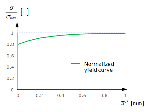
    In LAW83, the spotweld material curve may be input with fct_ID1. Where in LAW59 input, two yield curves for normal direction and shear direction are required, LAW83 uses just one curve. This curve should take the yield curve from shear test. Furthermore, the yield curve fct_ID1 for LAW83 is not defined as true stress versus plastic displacement (as in LAW59), but should be a normalized stress versus plastic displacement curve. Yield stress is normalized by maximum stress which are input as parameters R N , R S MathType@MTEF@5@5@+= feaagKart1ev2aqatCvAUfeBSjuyZL2yd9gzLbvyNv2CaerbuLwBLn hiov2DGi1BTfMBaeXatLxBI9gBaerbd9wDYLwzYbItLDharqqtubsr 4rNCHbGeaGqiVu0Je9sqqrpepC0xbbL8F4rqGqFfpeea0xe9vq=Jb9 vqpeea0xd9q8qiYRWxGi6xij=hbba9q8aq0=yq=He9q8qiLsFr0=vr 0=vr0db8meaabaqaciGacaGaaeqabaWaaeaaeaaakeaacaWGsbWaaS baaSqaaiaad6eaaeqaaOGaaiilaiaadkfadaWgaaWcbaGaam4uaaqa baaaaa@3BD3@ in LAW83.


    Figure 13.
    The yield curve is different due to different combinations of normal stress and shear stress in the spotweld. This may be described with parameter β in LAW83 (it is not considered in LAW59). The normalized yield stress in LAW83 is: (7) σ y = [ ( σ n R N f N ( 1 α sym ) ) β + ( σ s R S f S ) β ] 1 β MathType@MTEF@5@5@+= feaagKart1ev2aaatCvAUfeBSjuyZL2yd9gzLbvyNv2CaerbuLwBLn hiov2DGi1BTfMBaeXatLxBI9gBaerbd9wDYLwzYbItLDharqqtubsr 4rNCHbGeaGqiVu0Je9sqqrpepC0xbbL8F4rqqrFfpeea0xe9Lq=Jc9 vqaqpepm0xbba9pwe9Q8fs0=yqaqpepae9pg0FirpepeKkFr0xfr=x fr=xb9adbaqaaeGaciGaaiaabeqaamaabaabaaGcbaGaeq4Wdm3aaS baaSqaaiaadMhaaeqaaOGaeyypa0ZaamWaaeaadaqadaqaamaalaaa baGaeq4Wdm3aaSbaaSqaaiaad6gaaeqaaaGcbaGaamOuamaaBaaale aacaWGobaabeaakiabgwSixlGacAgadaWgaaWcbaGaamOtaaqabaGc daqadaqaaiaaigdacqGHsislcqaHXoqycqGHflY1ciGGZbGaaiyEai aac2gaaiaawIcacaGLPaaaaaaacaGLOaGaayzkaaWaaWbaaSqabeaa cqaHYoGyaaGccqGHRaWkdaqadaqaamaalaaabaGaeq4Wdm3aaSbaaS qaaiaadohaaeqaaaGcbaGaamOuamaaBaaaleaacaWGtbaabeaakiab gwSixlGacAgadaWgaaWcbaGaam4uaaqabaaaaaGccaGLOaGaayzkaa WaaWbaaSqabeaacqaHYoGyaaaakiaawUfacaGLDbaadaahaaWcbeqa amaalaaabaGaaGymaaqaaiabek7aIbaaaaaaaa@6268@
    In cases where the moment effect is not considered, the normalized yield stress in LAW83 is:(8) σ y = [ ( σ n R N f N ) β + ( σ s R S f S ) β ] 1 β MathType@MTEF@5@5@+= feaagKart1ev2aaatCvAUfeBSjuyZL2yd9gzLbvyNv2CaerbuLwBLn hiov2DGi1BTfMBaeXatLxBI9gBaerbd9wDYLwzYbItLDharqqtubsr 4rNCHbGeaGqiVu0Je9sqqrpepC0xbbL8F4rqqrFfpeea0xe9Lq=Jc9 vqaqpepm0xbba9pwe9Q8fs0=yqaqpepae9pg0FirpepeKkFr0xfr=x fr=xb9adbaqaaeGaciGaaiaabeqaamaabaabaaGcbaGaeq4Wdm3aaS baaSqaaiaadMhaaeqaaOGaeyypa0ZaamWaaeaadaqadaqaamaalaaa baGaeq4Wdm3aaSbaaSqaaiaad6gaaeqaaaGcbaGaamOuamaaBaaale aacaWGobaabeaakiabgwSixlGacAgadaWgaaWcbaGaamOtaaqabaaa aaGccaGLOaGaayzkaaWaaWbaaSqabeaacqaHYoGyaaGccqGHRaWkda qadaqaamaalaaabaGaeq4Wdm3aaSbaaSqaaiaadohaaeqaaaGcbaGa amOuamaaBaaaleaacaWGtbaabeaakiabgwSixlGacAgadaWgaaWcba Gaam4uaaqabaaaaaGccaGLOaGaayzkaaWaaWbaaSqabeaacqaHYoGy aaaakiaawUfacaGLDbaadaahaaWcbeqaamaalaaabaGaaGymaaqaai abek7aIbaaaaaaaa@5867@
    Figure 14 shows the difference of normalized maximum stress in combined tests between LAW83 and LAW59.
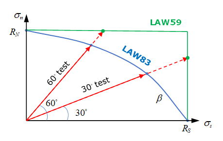

    Figure 14.
    Figure 15 shows the effect of varying β on normalized maximum stress in combined tests using LAW83.
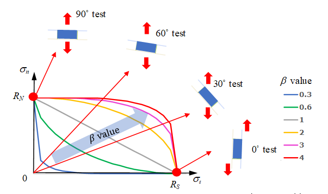

    Figure 15.
    Parameter α MathType@MTEF@5@5@+= feaagKart1ev2aqatCvAUfeBSjuyZL2yd9gzLbvyNv2CaerbuLwBLn hiov2DGi1BTfMBaeXatLxBI9gBaerbd9wDYLwzYbItLDharqqtubsr 4rNCHbGeaGqiVu0Je9sqqrpepC0xbbL8F4rqGqFfpeea0xe9vq=Jb9 vqpeea0xd9q8qiYRWxGi6xij=hbba9q8aq0=yq=He9q8qiLsFr0=vr 0=vr0db8meaabaqaciGacaGaaeqabaWaaeaaeaaakeaacqaHXoqyaa a@3907@ is used to describe the moment effect in the spotweld.
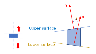

    Figure 16. Non-central tensile test (peel test)
    Use α sym MathType@MTEF@5@5@+= feaagKart1ev2aaatCvAUfeBSjuyZL2yd9gzLbvyNv2CaerbuLwBLn hiov2DGi1BTfMBaeXatLxBI9gBaerbd9wDYLwzYbItLDharqqtubsr 4rNCHbGeaGqiVu0Je9sqqrpepC0xbbL8F4rqqrFfpeea0xe9Lq=Jc9 vqaqpepm0xbba9pwe9Q8fs0=yqaqpepae9pg0FirpepeKkFr0xfr=x fr=xb9adbaqaaeGaciGaaiaabeqaamaabaabaaGcbaGaeqySdeMaey yXICTaci4CaiaacMhacaGGTbaaaa@3CC6@ to reduce the maximum stress of peel test. sym MathType@MTEF@5@5@+= feaagKart1ev2aaatCvAUfeBSjuyZL2yd9gzLbvyNv2CaerbuLwBLn hiov2DGi1BTfMBaeXatLxBI9gBaerbd9wDYLwzYbItLDharqqtubsr 4rNCHbGeaGqiVu0Je9sqqrpepC0xbbL8F4rqqrFfpeea0xe9Lq=Jc9 vqaqpepm0xbba9pwe9Q8fs0=yqaqpepae9pg0FirpepeKkFr0xfr=x fr=xb9adbaqaaeGaciGaaiaabeqaamaabaabaaGcbaGaae4CaiaabM hacaqGTbaaaa@38D8@ is the sin of the angle between the spotweld upper surface and lower surface. It is changed during spotweld deformation and is in range of [-1,1]. The α MathType@MTEF@5@5@+= feaagKart1ev2aqatCvAUfeBSjuyZL2yd9gzLbvyNv2CaerbuLwBLn hiov2DGi1BTfMBaeXatLxBI9gBaerbd9wDYLwzYbItLDharqqtubsr 4rNCHbGeaGqiVu0Je9sqqrpepC0xbbL8F4rqGqFfpeea0xe9vq=Jb9 vqpeea0xd9q8qiYRWxGi6xij=hbba9q8aq0=yq=He9q8qiLsFr0=vr 0=vr0db8meaabaqaciGacaGaaeqabaWaaeaaeaaakeaacqaHXoqyaa a@3907@ parameter may be fitted with a simple FEM model to match the real experiment data. 1
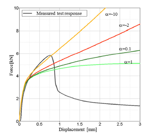

    Figure 17. Different α MathType@MTEF@5@5@+= feaagKart1ev2aqatCvAUfeBSjuyZL2yd9gzLbvyNv2CaerbuLwBLn hiov2DGi1BTfMBaeXatLxBI9gBaerbd9wDYLwzYbItLDharqqtubsr 4rNCHbGeaGqiVu0Je9sqqrpepC0xbbL8F4rqGqFfpeea0xe9vq=Jb9 vqpeea0xd9q8qiYRWxGi6xij=hbba9q8aq0=yq=He9q8qiLsFr0=vr 0=vr0db8meaabaqaciGacaGaaeqabaWaaeaaeaaakeaacqaHXoqyaa a@3907@ effects on peel test on force versus displacement

    The displacement rate effect on the material yield curve may also be considered with curve inputs fct_IDN and fct_IDS.

  • Material damage and failure:
    For spotweld failure, /FAIL/SNCONNECT may be used. In this failure model, the plastic displacement (in both normal and shear directions) of damage beginning and failure are needed.
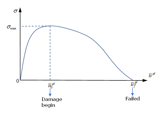

    Figure 18.
    For a combined mode test, similar to maximum stress in LAW83, β 0 MathType@MTEF@5@5@+= feaagKart1ev2aqatCvAUfeBSjuyZL2yd9gzLbvyNv2CaerbuLwBLn hiov2DGi1BTfMBaeXatLxBI9gBaerbd9wDYLwzYbItLDharqqtubsr 4rNCHbGeaGqiVu0Je9sqqrpepC0xbbL8F4rqGqFfpeea0xe9vq=Jb9 vqpeea0xd9q8qiYRWxGi6xij=hbba9q8aq0=yq=He9q8qiLsFr0=vr 0=vr0db8meaabaqaciGacaGaaeqabaWaaeaaeaaakeaacqaHYoGyda WgaaWcbaGaaGimaaqabaaaaa@39EF@ is needed to describe plastic displacement at damage beginning and β f MathType@MTEF@5@5@+= feaagKart1ev2aqatCvAUfeBSjuyZL2yd9gzLbvyNv2CaerbuLwBLn hiov2DGi1BTfMBaeXatLxBI9gBaerbd9wDYLwzYbItLDharqqtubsr 4rNCHbGeaGqiVu0Je9sqqrpepC0xbbL8F4rqGqFfpeea0xe9vq=Jb9 vqpeea0xd9q8qiYRWxGi6xij=hbba9q8aq0=yq=He9q8qiLsFr0=vr 0=vr0db8meaabaqaciGacaGaaeqabaWaaeaaeaaakeaacqaHYoGyda WgaaWcbaGaamOzaaqabaaaaa@3A20@ to describe plastic displacement at failure.
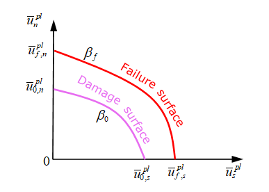

    Figure 19.
    For spotwelds with moment (peel test), similar to maximum stress in LAW83, α 0 MathType@MTEF@5@5@+= feaagKart1ev2aqatCvAUfeBSjuyZL2yd9gzLbvyNv2CaerbuLwBLn hiov2DGi1BTfMBaeXatLxBI9gBaerbd9wDYLwzYbItLDharqqtubsr 4rNCHbGeaGqiVu0Je9sqqrpepC0xbbL8F4rqGqFfpeea0xe9vq=Jb9 vqpeea0xd9q8qiYRWxGi6xij=hbba9q8aq0=yq=He9q8qiLsFr0=vr 0=vr0db8meaabaqaciGacaGaaeqabaWaaeaaeaaakeaacqaHXoqyda WgaaWcbaGaaGimaaqabaaaaa@39ED@ is needed to describe plastic displacement at damage beginning during the peel test and α f MathType@MTEF@5@5@+= feaagKart1ev2aqatCvAUfeBSjuyZL2yd9gzLbvyNv2CaerbuLwBLn hiov2DGi1BTfMBaeXatLxBI9gBaerbd9wDYLwzYbItLDharqqtubsr 4rNCHbGeaGqiVu0Je9sqqrpepC0xbbL8F4rqGqFfpeea0xe9vq=Jb9 vqpeea0xd9q8qiYRWxGi6xij=hbba9q8aq0=yq=He9q8qiLsFr0=vr 0=vr0db8meaabaqaciGacaGaaeqabaWaaeaaeaaakeaacqaHXoqyda WgaaWcbaGaamOzaaqabaaaaa@3A1E@ to describe plastic displacement at failure of peel test.
    Table 1. General Capability of the Two Spotweld Modeling Approaches
    /MAT/LAW59+/FAIL/CONNECT /MAT/LAW83+/FAIL/SNCONNECT
    Yield curve Two yield curves (in normal and shear directions) One normalized yield curve with maximum stress R N , R S MathType@MTEF@5@5@+= feaagKart1ev2aaatCvAUfeBSjuyZL2yd9gzLbvyNv2CaerbuLwBLn hiov2DGi1BTfMBaeXatLxBI9gBaerbd9wDYLwzYbItLDharqqtubsr 4rNCHbGeaGqiVu0Je9sqqrpepC0xbbL8F4rqGqFfpeea0xe9vq=Jb9 vqpeea0xd9q8qiYRWxGi6xij=hbba9q8aq0=yq=He9q8qiLsFr0=vr 0=vr0db8meaabaqaciGacaGaaeqabaWaaeaaeaaakeaacaWGsbWaaS baaSqaaiaad6eaaeqaaOGaaiilaiaadkfadaWgaaWcbaGaam4uaaqa baaaaa@3BD2@
    Maximum stress in combined mode test Normal and shear effect in combined test not considered. Use α MathType@MTEF@5@5@+= feaagKart1ev2aqatCvAUfeBSjuyZL2yd9gzLbvyNv2CaerbuLwBLn hiov2DGi1BTfMBaeXatLxBI9gBaerbd9wDYLwzYbItLDharqqtubsr 4rNCHbGeaGqiVu0Je9sqqrpepC0xbbL8F4rqGqFfpeea0xe9vq=Jb9 vqpeea0xd9q8qiYRWxGi6xij=hbba9q8aq0=yq=He9q8qiLsFr0=vr 0=vr0db8meaabaqaciGacaGaaeqabaWaaeaaeaaakeaacqaHXoqyaa a@3907@ to consider normal and shear effect in combined mode tests.
    Failure Failure criteria Displacement criteria Uni-direction failure

    Multi-direction failure

    Displacement criteria,

    Multi-direction failure

    Energy criteria Uni-direction failure

    Multi-direction failure

    Failure in combined mode test Proportionally controlled with α T , α N , exp T , exp N MathType@MTEF@5@5@+= feaagKart1ev2aqatCvAUfeBSjuyZL2yd9gzLbvyNv2CaerbuLwBLn hiov2DGi1BTfMBaeXatLxBI9gBaerbd9wDYLwzYbItLDharqqtubsr 4rNCHbGeaGqiVu0Je9sqqrpepC0xbbL8F4rqGqFfpeea0xe9vq=Jb9 vqpeea0xd9q8qiYRWxGi6xij=hbba9q8aq0=yq=He9q8qiLsFr0=vr 0=vr0db8meaabaqaciGacaGaaeqabaWaaeaaeaaakeaacqaHXoqyda WgaaWcbaGaamivaaqabaGccaGGSaGaeqySde2aaSbaaSqaaiaad6ea aeqaaOGaaiilaiGacwgacaGG4bGaaiiCamaaBaaaleaacaWGubaabe aakiaacYcaciGGLbGaaiiEaiaacchadaWgaaWcbaGaamOtaaqabaaa aa@4692@ in displacement criteria and with N n , N t MathType@MTEF@5@5@+= feaagKart1ev2aqatCvAUfeBSjuyZL2yd9gzLbvyNv2CaerbuLwBLn hiov2DGi1BTfMBaeXatLxBI9gBaerbd9wDYLwzYbItLDharqqtubsr 4rNCHbGeaGqiVu0Je9sqqrpepC0xbbL8F4rqGqFfpeea0xe9vq=Jb9 vqpeea0xd9q8qiYRWxGi6xij=hbba9q8aq0=yq=He9q8qiLsFr0=vr 0=vr0db8meaabaqaciGacaGaaeqabaWaaeaaeaaakeaacaWGobWaaS baaSqaaiaad6gaaeqaaOGaaiilaiaad6eadaWgaaWcbaGaamiDaaqa baaaaa@3C0C@ in energy criteria. Controlled with β 0 , β f MathType@MTEF@5@5@+= feaagKart1ev2aqatCvAUfeBSjuyZL2yd9gzLbvyNv2CaerbuLwBLn hiov2DGi1BTfMBaeXatLxBI9gBaerbd9wDYLwzYbItLDharqqtubsr 4rNCHbGeaGqiVu0Je9sqqrpepC0xbbL8F4rqGqFfpeea0xe9vq=Jb9 vqpeea0xd9q8qiYRWxGi6xij=hbba9q8aq0=yq=He9q8qiLsFr0=vr 0=vr0db8meaabaqaciGacaGaaeqabaWaaeaaeaaakeaacqaHYoGyda WgaaWcbaGaaGimaaqabaGccaGGSaGaeqOSdi2aaSbaaSqaaiaadAga aeqaaaaa@3D61@
    Moment effect

    (peel test)

    No control in input Controlled with α 0 , α f MathType@MTEF@5@5@+= feaagKart1ev2aaatCvAUfeBSjuyZL2yd9gzLbvyNv2CaerbuLwBLn hiov2DGi1BTfMBaeXatLxBI9gBaerbd9wDYLwzYbItLDharqqtubsr 4rNCHbGeaGqiVu0Je9sqqrpepC0xbbL8F4rqqrFfpeea0xe9Lq=Jc9 vqaqpepm0xbba9pwe9Q8fs0=yqaqpepae9pg0FirpepeKkFr0xfr=x fr=xb9adbaqaaeGaciGaaiaabeqaamaabaabaaGcbaGaeqySde2aaS baaSqaaiaaicdaaeqaaOGaaiilaiabeg7aHnaaBaaaleaacaWGMbaa beaaaaa@3BEB@
    Softening With T max , N s o f t MathType@MTEF@5@5@+= feaagKart1ev2aqatCvAUfeBSjuyZL2yd9gzLbvyNv2CaerbuLwBLn hiov2DGi1BTfMBaeXatLxBI9gBaerbd9wDYLwzYbItLDharqqtubsr 4rNCHbGeaGqiVu0Je9sqqrpepC0xbbL8F4rqGqFfpeea0xe9vq=Jb9 vqpeea0xd9q8qiYRWxGi6xij=hbba9q8aq0=yq=He9q8qiLsFr0=vr 0=vr0db8meaabaqaciGacaGaaeqabaWaaeaaeaaakeaacaWGubWaaS baaSqaaiGac2gacaGGHbGaaiiEaaqabaGccaGGSaGaamOtamaaBaaa leaacaWGZbGaam4BaiaadAgacaWG0baabeaaaaa@40CA@ (stress curve decreases) With reference to damage displacement and failure displacement (stress linear decrease)
1 Pasligh, N., Schilling, R., and Bulla, M., "Modeling of Rivets Using a Cohesive Approach for Crash Simulation of Vehicles in Radioss," SAE Int. J. Trans. Safety 5(2):2017, doi:10.4271/2017-01-1472