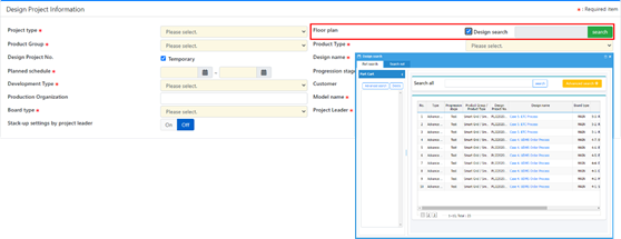
Floor plan: Using this function, user can copy the information of
existing project such as design name and model name. Check Design
search and click Search to find existing
design project. Figure 1.
After selecting design project, the information is copied to
new project.
Product Group: Select the product group.
Product Type: Select the product type.
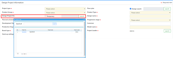
Design Project No.: Specify the design project number. The default
is that a new project number is generated by system temporarily, but
if the system is linked with the corporate system which manages
design projects, user can search and select the design project
number in the list from the corporate system. To select the project
number from the corporate system, disable the
Temporary checkbox and click
Search. Figure 2.
Design name: Specify a new design name.
Master schedule: Specify the master schedule from start to end
date.
Progress stage: Select the development progress stage.
Development Type: Select the development type.
Customer: Specify the customer of the design project.
Production Organization: Specify the department of production.
Model name: Specify the model’s name of the project.
Board type: Select the PCB type.
Project Leader: Select the project leader of the project.
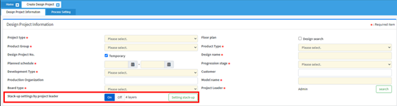
Stack-up settings by project leader: Set whether the project leader
sets the PCB layer stack-up settings. This option is displayed based
on the UDMS environment settings. For more information, contact your
system administrator. For setting the stack-up information, set this
option to Yes and click Setting
stack-up.
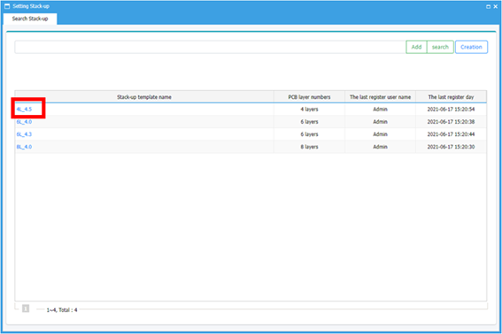
You can check the detail information by
clicking the stack-up template name. Figure 3.
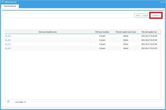
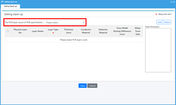
The project leader can create a
new stack-up information by clicking
Creation. Figure 4.
Select the layer count.
Figure 5.
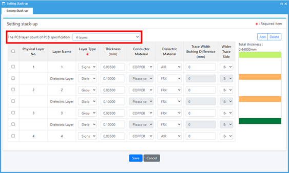
After selecting the layer count, the stack-up for the layer
counter will be shown automatically. This can be used as is or
modified. Figure 6.
Click Save to finish the
layer stack-up setting. Figure 7.
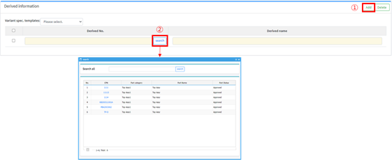
Derived information
Specify the variant information. This item is displayed only when
the creating variant in design project option is set to ON in the
UBMS environment. For more information, contact your system
administrator.
Add: Click Add to add a variant
information. Figure 8.