Inputs
1. Standard inputs
-
Line current, rms
The line current supplied to the machine: “Line current, rms” ( Line current, rms value ) must be provided.
-
Control angle
Considering the vector diagram shown below, the “ Control angle ” is the angle between the electromotive force E and the electrical current (J) (Ψ = (E, J)).
It is an electrical angle. The default value is 45 degrees. It must be set in a range of -90 to 90 degrees.
This range of values covers all the possible working point in motor convention.
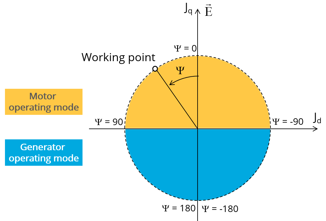
Definition of the control angle Ψ - Motor convention -
Speed
The imposed “ Speed ” ( Speed ) of the machine must be set.
-
Represented coil conductors
In transient application, it is possible to export a project into Flux environment where the elementary wires will be modeled with solid conductors. The geometry, the meshing and the corresponding electric circuit will be defined to well represent them.
One choice is possible:
- “All phases”: The elementary wires will be represented into all the phases
2. Advanced inputs
The list of advanced inputs dedicated to this export are listed below.
For more details, please refer to the section dedicated to the list of generic advanced inputs.
-
Number of computations per electrical period
The default value is equal to 50. The minimum allowed value is 13.
-
Number of computed electrical periods
The default value is equal to 2. The minimum allowed value is 1 and the maximum value is equal to 10.
-
Rotor initial position
By default, the “ Rotor initial position ” is set to “ Auto ”.
-
Mesh order
The default level is second order mesh
-
Airgap mesh coefficient
Airgap mesh coefficient is set to 1.5 by default.