Zero initialization: transient numeric problem
Problem: transient numeric
There is a certain number of situations in which “the starting” of the simulation and the taking into consideration of all the pieces of information at the initial time t = 0 s are not carried out “in real accordance with the physical reality”.
The starting is accompanied then by a “numeric transient”, which distorts the solving process. This “numeric transient” has the following shortcomings:
- increase of calculation time
- false results over the first time steps
- convergence problems (essentially in 3D)
The “at risk” situations are the following ones:
- magnet or non null sources of current at the initial time t = 0 s
- solid conductors and/or coil conductors coupled with electric circuit
What happens when there are non null sources at t = 0 s ?
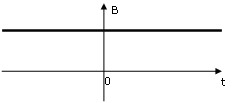
When there are non-null sources of field at time t = 0 s (magnets or currents), these sources are not always correctly taken into account in the Flux model.
- In Flux: the initial values of the state variables (starting point of calculation) are zero in all computation domains (variables set at zero).
- In reality: the field sources (permanent magnets or currents) « produce » field before the moment of the study starting (t = 0 s)
Complementary explanations in the table below.
| In reality | In the Flux simulation |
|---|---|
| The permanent magnet « produces field » since it is positioned /introduced into the device | The permanent magnet « produces field » since the moment when the study begins (initial time t = 0 s) |

|
|
Consequence :
The numerical evaluation of the derivative dΦ/dt is not correct in the simulation in proximity of initial time t = 0 s.
-
at the first time step t = t1 :
the value of the quantity dΦ/dt is very important, because
 is very
important
 -
at the second time step t = t2 :
the value of dΦ/dt is much more reduced, because
 is reduced
At the level of Flux conductors
At the level of Flux magnetic field sources (coil or solid conductors), the relationship connecting the current and the voltage is the following:
![]()
If there are magnets in the device, the value in d Φ /dt is not correct in the simulation in proximity of t = 0 s, which generates a numeric overvoltage at the conductor terminals.
This overvoltage can be explained by the fact that at the first time step the magnetic flux in the coils varies from the initial zero value to the first time step (flux created by the magnet); as explained in the previous block, this variation is very important.
At the level of passive components
At the level of passive components of the inductance or capacitor type, the relationships linking the current and the voltage are reminded in the table below.
If there is over-voltage or over-current in the proximity of initial time t = 0 s, the values of the derivatives dI/dt et dU/dt are also wrong.
| Component |
Current-voltage characteristic |
Characteristic quantity | Initial value |
|---|---|---|---|
| inductor |
|
L is the value of the inductance (in H) | Not implemented |
| capacitor |
|
C is the value of the capacitance (in F) |
Initial voltage U (t = 0) |
Presentation
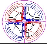
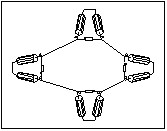
The studied device is a dynamo.
|
Computation conditions |
Finite Elements domain | Electric circuit |
|---|---|---|
|
 |
 |
Results
The voltage measured at the terminals of one of the coils is represented in the figure below. The reference results and the Flux results are presented in the table below.
| Reference voltage | Voltage calculated in Flux |
|---|---|
|
|
|
| Voltage oscillation around 20 V | Over-voltage of 150 V |
An initial overvoltage of about 150 V is observed in Flux. This overvoltage is due to the fact that, at the first time step, the variation of the magnetic flux in the coils between the initial (no flux) and the first time step (flux created by the magnet) is very important. This overvoltage, of numerical origin, has no physical meaning, and it can be at the origin of a numerical transient altering the simulation.