Run an SLM Analysis
Run an SLM additive manufacturing analysis for the selcted print parts.
Before running a selective laser melting analysis, you must
first select the parts to be printed, set up the printer, and define the part
orientation and supports.
-
Click the
 button on the Analyze
icon.
button on the Analyze
icon.

Tip:
- Click
 on the Analyze icon to view the run status.
Runs that are being processed or that have not been viewed are shown in the
Run Status table.
on the Analyze icon to view the run status.
Runs that are being processed or that have not been viewed are shown in the
Run Status table. - Click
 on the Analyze icon to view the run history.
Runs that have been viewed previously are shown in the Run
History table.
on the Analyze icon to view the run history.
Runs that have been viewed previously are shown in the Run
History table. - The
 icon indicates that the run was
incomplete. Some but not all of the result types may be available. You
should run a new analysis to generate complete results.
icon indicates that the run was
incomplete. Some but not all of the result types may be available. You
should run a new analysis to generate complete results. - To view multiple runs, hold the Ctrl key while selecting runs, then click the View Now button. If several runs are associated with the same part, the result from the most recently completed run for that part will be activated in the modeling window.
- To open the directory where a run is stored, right-click the run name and select Open Run Folder.
Process Parameters
Process parameters impact what result types are available at the end of the simulation, as well as the processing time and accuracy of results.
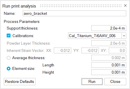
- Supports thickness
- The thickness of a printed support's outer shell. The number will depend on the printer being used.
- Calibrations
- Enable this option to select available calibrations from the dropdown menu.
- Powder layer thickness
- For powder-based 3D printing processes, this indicates the thickness of the powder layer that is spread across the printing bed. This information is unique to the printer model and should be available from your 3D printer.
- Inherent Strain Vector
- This represents a symmetric tensor written in vector form, with components
[XX, YY, XY]. The values in these fields represent the material's shrinkage
in all directions as it cools. Note: These parameters are only available for analyses in which the Calibrations option is not selected.
- Average thickness
- The simulation's results are shown as a voxel mesh. You can enter either an average thickness or an element size for the mesh.
- Element size
- If you choose to define the voxel mesh in terms of element size, enter a length and height. A good starting point is generally 1 x 1 mm. Reducing the voxel size improves accuracy, but increases the time of the analysis.