Bushings
Create bushings between the selected surfaces of the parts.
Create Bushings
Bushings can only be created between two surfaces of two parts. You need to define at least the linear or rotational stiffness. Mass is optional.
-
On the Structures ribbon, select the Bushings
tool.

-
Click Create the Bushing
 .
.
-
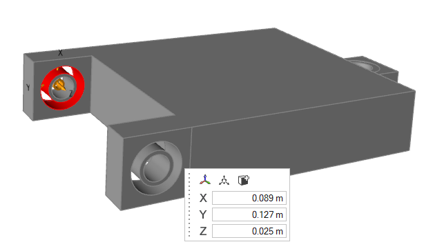
In the microdialog, you can do the following:
Option Description Align to Global Axes 
Align to the global axes. Move 
Translate or rotate using the Move tool. Add/Remove 
Add/remove faces from the selected bushings. Set Origin X Set the origin coordinate in the X direction. Set Origin Y Set the origin coordinate in the Y direction. Set Origin Z Set the origin coordinate in the Z direction.
Edit Bushings
Select one or more bushings to change their properties.
To review all bushings and edit their names and properties in one place, see Open the Bushings Table.
-
On the Structures ribbon, select the Bushings
tool.
-
Click Create the Bushing
.
The changes will be applied.
-
In the microdialog, you can do the following:
Option Description Align to Global Axes Align to the global axes. Move Translate or rotate using the Move tool. Add/Remove Add/remove faces from the selected bushings. Set Origin X Set the origin coordinate in the X direction. Set Origin Y Set the origin coordinate in the Y direction. Set Origin Z Set the origin coordinate in the Z direction.
Open the Bushings Table
Review all bushings and edit their names and properties in one place.
-
On the Structures ribbon, select Open Bushings
Table.

The Bushings table is displayed.