Displacement Constraints
Displacement constraints can be applied to a model to limit deflections in desired locations and directions.

You can choose to limit displacement in one direction or in all directions, as shown in the images below. A displacement constraint in one direction can have an upper bound, lower bound, or both.
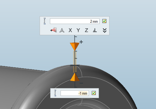
Displacement Constraint in One Direction with an Upper and a Lower Bound
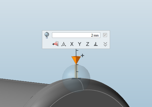
Displacement Constraint in All Directions
Apply a Displacement Constraint in All Directions
- Displacement constraints should only be applied to non-design spaces.
- While they can be used as the sole constraint for an optimization, we recommend using displacement constraints alongside a stress constraint.
- Use the right-click context menu to include or exclude a displacement constraint from a load case.
Apply a Displacement Constraint in a Single Direction
- Displacement constraints should only be applied to non-design spaces.
- While they can be used as the sole constraint for an optimization, we recommend using displacement constraints alongside a stress constraint.
- Use the right-click context menu to include or exclude a displacement constraint from a load case.
Microdialog Options
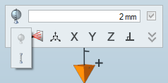
Double-click on a displacement constraint to enter editing mode, which opens a microdialog.
|
|
Apply the displacement constraint in one direction or all directions. |

|
Enter a magnitude or upper and/or lower bound for the displacement constraint. When applying in one direction, use the check boxes to define whether to use a lower and/or upper bound. |
|
|
Click the icon to enter/exit Multi-Selection mode. In this mode, you can click a feature to add/remove it from the selection. Outside of this mode, you need to hold down Ctrl while clicking. |
|
|
Translate or rotate the displacement constraint using the Move tool. |
|
|
Align the displacement constraint to an axis or normal to the face. |
|
|
Click to orient the displacement constraint by entering component vectors for x, y, and z. (For example, entering 1, 0, 0 would orient it in the positive x direction.) |
FAQs: Displacement Constraints
Find answers to frequently asked questions about displacement constraints.
Why Are My Results Disconnected?
When you use displacement constraints, it is important to either apply them near all of the major loads or to use both stress constraints and displacement constraints together.
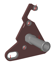
Figure 1. Original Model
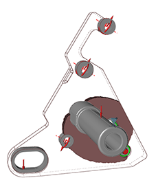
Figure 2. Displacement constraint of 2 mm at the foot peg with no stress constraint
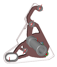
Figure 3. Displacement constraint of 2 mm at the foot peg with a stress constraint

 button and enter a
value in the text fields of the microdialog, to change the magnitude of the
upper or lower bound for the displacement constraint.
 on
the microdialog, then click and drag the arrows or enter a precise value in
the text box.
 button to revert to the default
direction.


