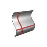
Face Curve

Extract curves from a face in the U or V direction. This is useful for creating trim curves that run along a face.

Face curves can also be used to recreate a given surface with different parameterization. Extract several face curves and use the Loft tool to create a surface through them. A face curve extracted from a surface can be used as a snappable location when you need to place an object on such a surface.

  1. On the Geometry ribbon, select the Face Curve tool.

    Note: The tool may be hidden in a dropdown menu. To access the dropdown menu, you can do one of the following:
    • Click and hold the currently displayed tool (NURBS, Blend, Helix, Extend Curve, or Divide).
    • Select at the lower right corner of the currently displayed tool (NURBS, Blend, Helix, Extend Curve, or Divide).
    The guide panel appears.


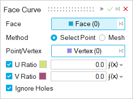
  2. By default, the Face button is automatically selected. Select a face on which you want to extract curves. To deselect, hold down Ctrl while clicking or, in the guide panel, click .
  3. Choose a method:
    • Select Point/Vertex: Select a point or vertex to create the curves. To deselect, hold down Ctrl while clicking.
    • Mesh Mode: Create curves in a mesh pattern.
  4. Based on the method previously selected, create and adjust the curves.
    Note: The color next to the U and V options indicate the color of the curves in the respective direction. Face curves in the U direction are displayed in yellow while face curves in the V direction are displayed in magenta.
    Method Do this
    Select Point/Vertex
    1. Next to Point/Vertex, select the Vertex button.
    2. Select a point or vertex.
    3. To create curves along the U or V direction, turn on U Curves and V Curves. To disable curves along the U and V direction, turn off the respective option.
    4. To position the curve along the U or V direction, enter a value of 0 to 1 for the U Ratio or V Ratio.
    5. To not draw curves through holes on the face, turn on Ignore Holes.
    Mesh Mode
    1. To create curves along the U or V direction, turn on U Curves and V Curves. To disable curves along the U and V direction, turn off the respective option.
    2. To enter the number of curves along the U or V direction, enter a a value for Number of U Curves or Number of V Curves.
    3. To not draw curves through holes on the face, turn on Ignore Holes.
  5. In the guide bar, select Apply .
  6. Right-click and mouse through the check mark to exit, or double-right-click.