Creating an application for machines with continuous skewing
Introduction
In a Flux Skew project, the type of skewing (i.e., continuous or step) of a machine is a property of the application.
This chapter discusses the creation of a Flux Skew application for machines with
continuous skewing (or skewed slots). The following subjects are covered:
- How to create an application with continuous skewing.
- Example of application.
How to create an application with continuous skewing
The procedure to create an application in Flux Skew is similar to Flux 2D and Flux
3D. However, the following particularities should be remarked:
- Only magnetic applications exist in Flux Skew, as discussed in the topic: Flux Skew magnetic applications.
- For all applications in Flux Skew, the Definition tab of the application creation window contains a Skewing definition section. This section must be completed with construction parameters of the skewed machine.
To describe a machine with continuous skewing, the Skewing definition section
should be completed as follows:
- Skewed mechanical set: in this drop-down menu, the user must choose
between Fixed mechanical set and Rotating mechanical set.
Note: Only the regions linked to the chosen mechanical set will be subjected to skewing. This option allows distinguishing between machines with skewed rotors (usually linked to a rotating mechanical set) or skewed stators (usually linked to a fixed mechanical set).
- Skewing type: in this drop-down menu, the user must choose Continuous skew
- Topology description: two approaches are available, namely the Simple (homogenous layers) method and the Advanced (layer by layer) method.
- The Simple (homogenous layers) description method is straightforward
and requires only three parameters (accordingly with part (a) of Figure 1):
- the Length unit allowing to choose the unit (or to create a new one) for the Axial length;
- the Axial length;
- the Rotation angle or skew angle, in degrees;
- the Number of layers along the axial length, or the axial
discretization of the skewed machine after its 3D reconstruction (in
post-processing). Note: This parameter also corresponds to the total number of linked 2D finite element problems solved by Flux Skew along the axial length of the machine during resolution, as discussed in the topic: What is Flux Skew?
- The Advanced (layer by layer) method is also available and allows the
description of more complex topologies (V skewing, for instance). In this
approach, the user must fill a table in which each line represents a skewed
layer. Two parameters are required for each layer (accordingly with part (b)
of Figure 1):
- the Length unit allowing to choose the unit (or to create a new one) for the Layer thickness;
- the Layer thickness;
- the Layer skewing angle, in degrees.
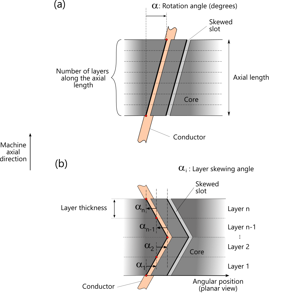
Figure 1. Planar representation of the magnetic core (either the rotor or stator) of an electrical machine with skewed slots. The parameters required by Flux Skew to describe the topology of a machine with continuous skewing are highlighted, the Simple description in (a), and the advanced description in (b).
The remaining tabs of the application creation window are similar to their Flux 2D and Flux 3D counterparts and depend on the specific application chosen by the user.
Once the description of the application is completed, the user is ready to proceed with the 2D description of a rotating electric machine with continuous skewing in Flux Skew's environment.
CAUTION:
For magnets described as solid conductors in
continuous skew, the currents flowing into them behave as if they are segmented at
layer interfaces. In other words, Flux Skew cannot account for the current flowing
into these magnets through the layers. To model this phenomenon, the use of Flux 3D
module is required.