HWCFD-T: 1010 Wrapping Workflow
Before you begin, copy the file(s) used in this
tutorial to your working directory.
Group the Solids to be Wrapped
-
While holding the Ctrl key,
select the solids depicted in the figure below.
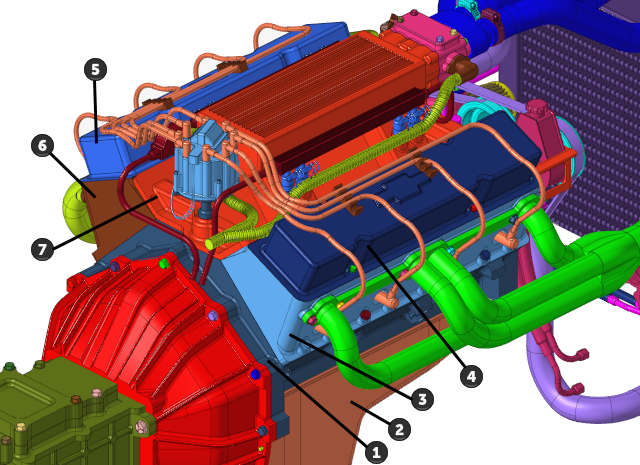
Figure 1. -
From the Assembly ribbon, click the Group tool.

Figure 2. -
Make sure that you have 7 parts selected by observing the number in parentheses
on the guide bar selector.
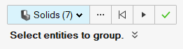
Figure 3. -
On the guide bar, click
 to execute the command and remain in the
tool.
to execute the command and remain in the
tool.
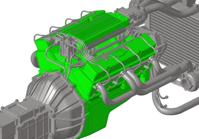
Figure 4. -
On the guide bar, click
 to exit
the tool.
to exit
the tool.
Convert CAD Geometry to an FE (Tessellated) Model
-
From the Home tools, click the Convert tool.

Figure 5.The Convert CAD to FE dialog opens. -
Ensure that Faceting is selected for the Unmeshed
surface meshing method and that the faceting size definition is set to
Normal.
Figure 6.
Cap Holes and Other Openings
Small holes and other openings which only increase the mesh count and do not contribute to the simulation are capped/closed off before the wrapping of the geometry is done.
-
From the Discrete ribbon, click the tool.

Figure 7. -
Select all surfaces on the screen using one of the following methods:
- Left-click and drag over the entire model.
- Press Ctrl + A.
Ensure that you have 2925 surfaces displayed on the guide bar's surface selector.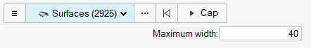
Figure 8. -
Select the four nodes shown in Figure 9.
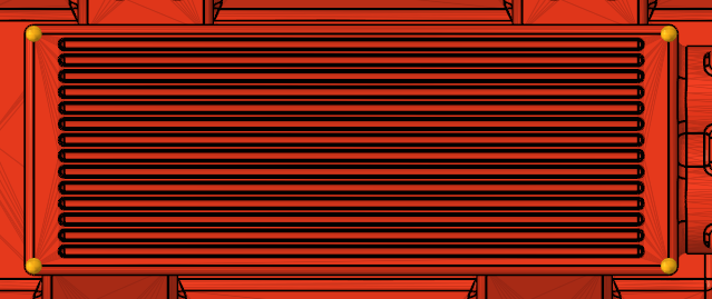
Figure 9. -
Click the tool.

Figure 10. -
In the dialog, set the wrapping method to Tight Wrap,
enter the value of 20 for the Average element size, and
leave all other options as their default values.
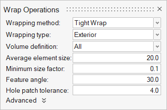
Figure 11.
Re-mesh Wrapped Results
-
From the Discrete ribbon, click the Remesh tool.

Figure 12. -
In the dialog, set the Average size to 20 and leave all
other options as their default values.
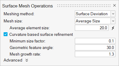
Figure 13.
Fix Wrapped Geometry
-
From the Discrete ribbon, click the Auto Repair
tool.
 Figure 14.
 -
Click
 on the guide bar. Ensure
that Intersection cleanup is checked.
on the guide bar. Ensure
that Intersection cleanup is checked.
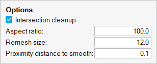
Figure 15. -
Save the model.
Figure 16.