Random Response Fatigue Analysis
The study of fatigue life of structures under Random Loading.
Power Spectral Density (PSD) results from the Random Response Analysis are used to calculate Moments () that are used to generate the probability density function for the number of cycles versus the stress range.
- by using PSD Stresses which are already available for Random Fatigue
- by using PSD Stresses generated from Frequency Response Analysis and Power Spectral Density Functions Loading versus Frequency in HyperLife
PSD Stresses Are Already Available for Random Fatigue
The PSD Moments are calculated based on the Stress PSD generated from the Random Response Analysis, as shown below.
Input
Calculates Random Response Fatigue.
Power Spectral Density (PSD) Moments

Figure 1. Calculation of PSD Moments
- Frequency value
- PSD response value at frequency
The stability of can be checked by setting PARAM, CHKM0, YES. A warning is printed if the frequency interval must be further refined.
Calculate Probability of Stress Range Occurrence
Calculation of the Probability of occurrence of a stress range between the initial and final stress range values within each bin section are user-defined.
The probability of a stress range occuring between and is .
Probability Density Function (probability density of number of cycles versus stress range)
PSD Moments calculated as shown above are used in the generation of a Probability Density Function for the stress range. The function is based on the specified damage model in the Random Response Fatigue section of the SN Fatigue module. Currently, DIRLIK, LALANNE, NARROW, and THREE options are available to define the damage model.
- Irregularity Factor
- Stress range
- Irregularity factor
- Stress range
Where, is the stress range.
In the NARROW band model, by default, HyperLife uses number of zero crossings () instead of number of peaks (), because the numerical calculations involving may lead to unstable numerical behavior.
The Steinberg 3-Band Random Fatigue Damage model uses the following probability function.
Where, is the stress range.

Figure 2. Probability Density Function (probability density of number of cycles versus stress range)
- Upper Stress Range (Calculated)
- Calculates the upper limit of the stress range. This is calculated as: upper limit of the stress range = 2*RMS Stress*Upper Stress Range (Calculated) input. The RMS Stress is output from Random Response Subcase. The stress ranges of interest are limited by the upper limit of the stress range. Any stresses beyond the upper limit are not considered in Random Fatigue Damage calculations.
- Width: Stress Range (Calculated)
- Calculates the width of the stress ranges (DS = ) for which the probability is calculated (Figure 2). The default is 100 and the first bin starts from 0.0 to . The width of the stress range is calculated as DS = upper limit of the stress range / Width: Stress Range (Calculated).
Calculate Probability of Stress Range Occurrence
Calculation of the Probability of occurrence of a stress range between the initial and final stress range values within each bin section are based on the damage models.
The probability of a stress range occurring between and is .
Where, is stress range.
For the THREE damage model, there are only three bins. The number of cycles at each stress range (2*RMS, 4*RMS, and 6*RMS) are calculated by directly multiplying the corresponding probabilities with the total number of zero-crossings (refer to section below regarding calculation of number of zero-crossings).
Select Damage Models
- You can see from the previous sections, that the PSD moments of stress are used to calculated corresponding moments, which are used to determine the probability density function for the stress-range.
- DIRLIK and LALANNE models generate probabilities across a wider distribution of the stress-range spectrum. Therefore, these models should be used when the input random signal consists of a variety of stress-ranges across multiple frequencies. Therefore, the information in the probability density function better captures the wider range in stress-range distribution if DIRLIK and LALANNE are used.
- The NARROW model is intended for random signals for which the stress range is expected to be closely associated with a high probability of particular certain stress range distribution. Therefore, if you know that the input random data does not have a wide range of stress-range distribution, and that the distribution is mainly concentrated about a particular stress range, then you should select NARROW, since it expects the highest probability of stress-ranges to lie at or around this particular stress range.
- The THREE model is like the NARROW model, except that it expects the distribution of the random signal to contain, in addition to the association with 1*RMS, associations (albeit smaller) with 2*RMS, and 3*RMS. Therefore, if your input random data is mainly clustered around stress ranges in 1*RMS, and to a lesser extent, 2*RMS, and 3*RMS, then you should select THREE.
Number of Peaks and Zero Crossings
Where, is the corresponding moments calculated, as shown in Power Spectral Density (PSD) Moments.
Where, is Total exposure time given by the Repeats/Time values when creating events in the Load Map dialog.
Fatigue Life and Damage
To account for the mean stress correction with any loading that leads to a mean stress different from zero, you can define a static subcase that consists of such loading (typically gravity loads). This static subcase can be referenced within the fatigue event created in the Load Map dialog.
Setup

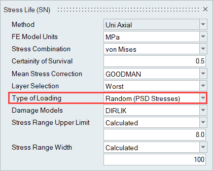
Figure 3.
PSD Stresses to be Generated from Frequency Response Analysis and Power Spectral Density Functions Loading vs Frequency in HyperLife for Random Fatigue
The PSD stresses are calculated internally using the FRF stresses and the input PSDs. The fatigue event created first calculates the PSD stress (Random Response Analysis), which are then used to calculate the PSD moments.
Different Load Cases (a and b)
Where, is the cross power spectral density of two (different, ) sources, where the individual source is the excited load case and is the applied load case. This value can possibly be a complex number.
Same Load Case (a)
Combination of Different (a,b) and Same (a,a) Load Cases in a Single Random Response Analysis
If there is a combination of load cases for Random Response Analysis, the total power spectral density of the response will be the summation of the power spectral density of responses due to all individual (same) load cases as well as all cross (different) load cases.
Setup
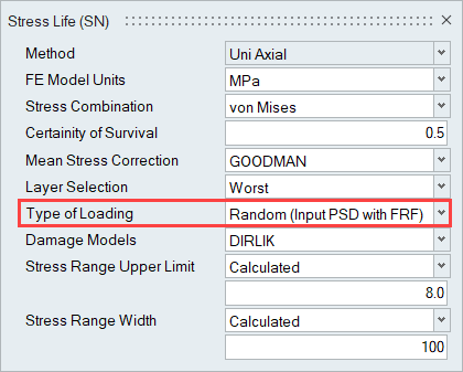
After loading an FE result file that contains a Frequency Response Analysis subcase, Random Response Fatigue is activated by setting the Type of Loading field to Random (Input PSD with FRF).

Figure 4.
Loadmap:
- Input PSD: Real and Imaginary
- Input PSD: Magnitude and Phase

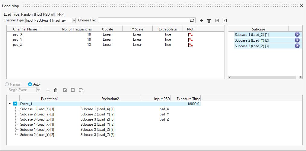
Figure 5. Event Creation in the Load Map Dialog for Random Fatigue with FRF Stresses and Input PSD
Excitation1 and Excitation2 refer to the correlations of the FRF subcases. The Input PSDs are used to scale the complex stresses. If the Input PSDs are of the Phase and Magnitude form, they are internally converted to Real and Imaginary.
PSD Stresses calculated from the above event are then utilized for fatigue calculations, like the case where PSD stresses are already available (described in the beginning of this chapter).