Injection Mold Mapping
Use the Injection Molding ribbon to facilitate the development of accurate structural simulation models for reinforced injection molded parts and assemblies.
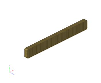
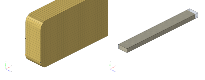
The injection molding – structural simulation workflow is described graphically in Figure 1. Definitions for the mold simulation space and structural simulation space are defined in Figure 2 and used consistently throughout describing the process. The starting point for this workflow is an injection molding simulation of a reinforced part or assembly.
The output from the injection molding simulation is the mold mesh in OptiStruct (*.fem), Patran (*.pat), or Abaqus (*.inp) format, and the fiber orientation tensor results file in Altair Inspire Mold (*.xml), Moldflow (*.xml), or Moldex3D (*.o2d) formats.
The fiber orientation tensor results from the molding simulation must be mapped from the mold mesh to the structural mesh, which can be in any of OptiStruct (*.fem), Radioss (*.rad), Abaqus (*.inp), or LS-DYNA (*.k) formats. The mapping process is performed in HyperWorks using the injection molding ribbon. The output of the fiber orientation tensor mapping process is heterogeneous fiber orientation tensor data (*_mdsFOT.dat) and a material orientation system (*_mdsMATORI.dat) on the Structural Mesh in the Altair Multiscale Designer format.
When coupled with an Altair Multiscale Designer discontinuous fiber material model (*_mdsMAT.dat), a full heterogeneous anisotropic thermos-mechanical structural simulation can be performed. Each step of the injection molding – structural simulation workflow is described further below.
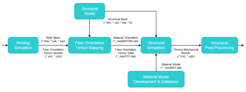
Figure 1. Injection Molding – Structural Simulation Workflow
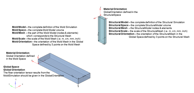
Figure 2. Fiber Orientation Tensor Mapping Definitions for the Mold Space and Structural Space
The intention of the Injection Molding ribbon is to work from left to right through the workflow for each injection molded part or a possible assembly individually. It is not suggested to go backwards in steps, and some steps exclude going back. However, some steps can be run multiple times if incorrect data is entered in the execution of the current or prior step. The intended workflow (order) of the steps as given on the ribbon from left to right is:
- 1. Import Mold Mesh
- Can rerun but should “Create New Model” before rerun.
- 2. Create Orientation Field
- Can run multiple times; each time creates a new field; only one of fields can be used. The last field generated is automatically selected.
- 3. Process Mold Mesh
- Can only run once and after execution cannot perform any prior step; must move to Import Structural Mesh step, or, “Create New Model” and start over from beginning.
- 4. Import Structural Mesh
- Can rerun but should “Delete Components” first.
- 5. Process Structural Mesh
- Can execute multiple times until Structural Mesh is positioned in Mold Space correctly but cannot redefine Mold Mesh points only Structural Mesh points.
- 6. Map and Export
- Can be executed multiple times; will overwrite files from previous execution.
Import Mold Mesh
Import the mold simulation mold mesh in either OptiStruct (*.fem), Patran (*.pat), or Abaqus (*.inp) formats.
Create Orientation Fields
Create a field of fiber orientation tensor results on the mold mesh given a fiber orientation tensor results file (Altair Inspire Mold *.xml, Moldflow *.xml, or Moldex3D *.o2d) consistent with the current loaded model (imported mold mesh).
Process the Mold Mesh
Obtain mold mesh information required to map fiber orientation tensors to the structural mesh.
Import Structural Mesh
Import the structural simulation structural mesh in either OptiStruct (*.fem), Radioss (*.rad), Abaqus (*.inp), or LS-DYNA (*.k) formats
Process Structural Mesh
Scale and position the structural mesh into the mold space.
Map and Export Data
Map fiber orientation tensor results from the mold mesh to the structural mesh and export mapped fiber orientation tensor data on the structural mesh for Multiscale Designer material models.
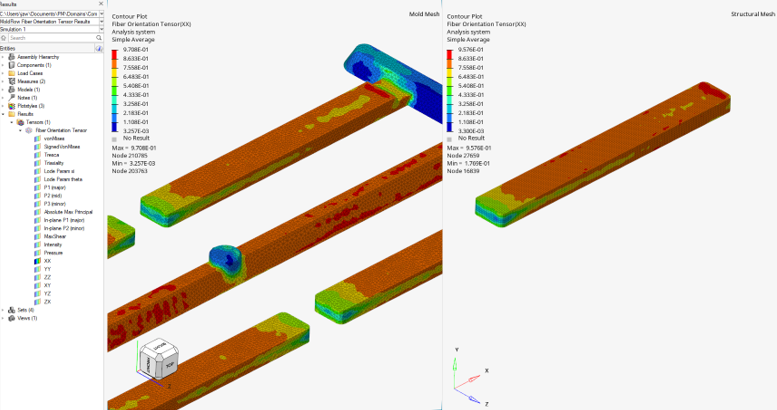
Visualize Mapped Fiber Orientation Tensors for Qualitative Assessment
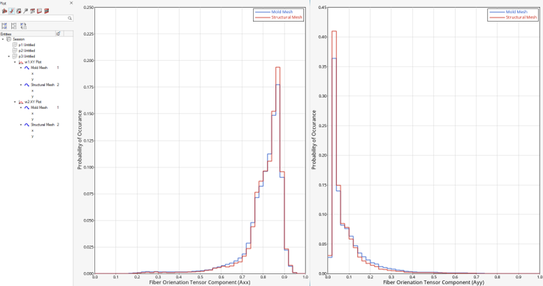
Plot Histogram Data for Qualitative Assessment
Assign Material Orientation to Structural Mesh
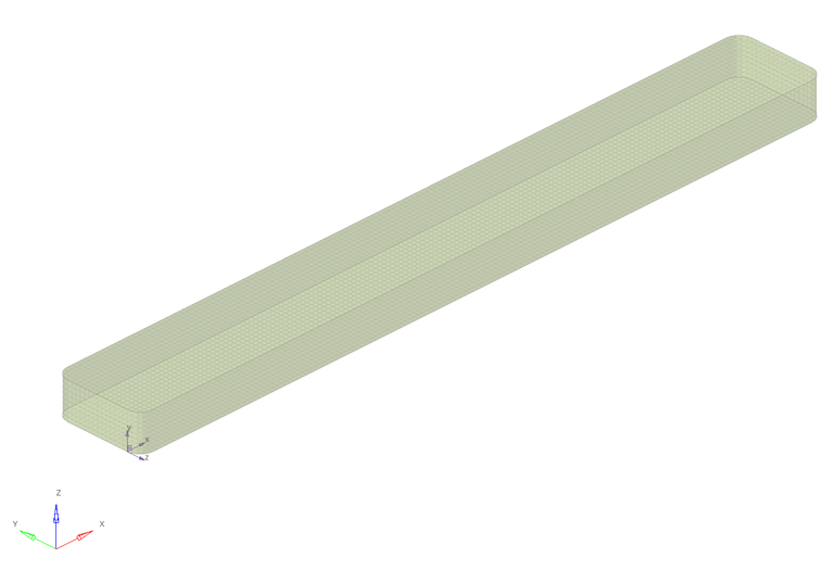
Figure 17. Structural Mesh in Structural Space with Material Orientation Imported

