Smooth Particle Hydrodynamics Meshing

Smooth Particle Hydrodynamics (SPH) is a technique used to analyze bodies that do not have high cohesive forces among themselves and undergo large deformation, such as liquids and gases.

Restriction: Available in the Radioss, PAM-CRASH 2G, and LS-DYNA solver interfaces.

In SPH Finite Point Method (SPH FPM), a given volume of the body of interest is discretized into particles, called SPH elements. These elements are node-like particles which have no geometric connectivity among themselves. Each SPH element has an effective mass. The summed mass of all particles in the filled volume of the body should be equal to the mass of the filled volume.

Create SPH Mesh

Perform SPH analysis on a component with volume, such as airbags or fuel tanks.

  1. From the Mesh ribbon, click the arrow next to the 2D Mesh tool set name and select SPH from the list of options.
    The SPH controller opens.
  2. Select the entities that define the volume to be filled with SPH elements.
  3. Optional: SPH elements are generated at the corners/face centers of the cubes which fall within the user-defined criteria. Check Use reference to specify which point the generation of cubes should be started.
    The base point defines the starting point for cube generation, and is utilized by the mesher as a starting point.
    Global origin
    Uses (0, 0, 0) for the reference point.
    Local origin
    Define a node for the reference point.
  4. Choose a method for defining the orientation of SPH elements.
    Global system
    Use the default global system to align generated SPH elements.
    Local system
    Define reference systems local to the model orientation. Generated SPH elements are aligned using the user-defined local system.
  5. Choose a pitch method for specifying the distances between each SPH particle.
    Simple cubic
    Arrange SPH particles in groups of 8, each particle being a corner of a cube.
    Face centered cubic
    Arrange the particles in groups of 14, forming the corners and the center of each face of a cube.
    This is similar to a hexagonal close packed (HCP) structure and is recommended for use in Radioss models.
    Note: Smaller numbers will result in more elements within the same space, but this will not affect the mass or density of the substance (gas, fluid, and so on) that the particles represent.
  6. Choose a mass definition and method for specifying the quantity of fluid.
    Material density
    Specify its density (the total mass is then determined by the volume filled).
    Filled volume mass
    Specify its total mass (volume and density is determined by the model volume filled).
  7. Choose which elements to generate SPH elements for.
    All
    Generate SPH elements in all of the volumes in the model.
    Enclosed
    Generate SPH elements in the volumes enclosed by the defined nodes, and ignores the remaining volumes.
    Nth Largest
    Specify which volumes to generate SPH elements in by defining the wrap size index in terms of volume size.
    Specify the largest volume by entering 1; specify the second largest volume by entering 2.
    Exclude enclosed
    Ignore the volume(s) enclosed by the defined nodes and generate SPH elements in the remaining volumes.
  8. Choose which components new elements are created in.
  9. Optional: Check Partial fill to model a fluid or gas that does not completely fill the selected volume.
    If enabled, perform the following steps:
    1. Choose between percent and depth.
      Percent
      Percentage of the volume to fill.
      Depth
      Depth of the volume to fill.
    2. Specify a percentage/depth of the volume to fill. Calculation of the volume is based on the lowest point of the model, parallel to the user-defined plane.
    3. Use the plane and vector tool to define the direction of fill, which is generally the opposite of the direction of gravity when the filled volume is installed in the real world.
    4. If the particle mass is filled along the correct axis, but in the wrong direction (for example from the top of a fuel tank downward) check Reverse direction to fix this.


    Figure 1.
  10. Optional: Check Wall offset to create SPH particles up to a distance that you specify.
    The thickness of SPH elements is created from input. The distance between the SPH particles is driven by the pitch.
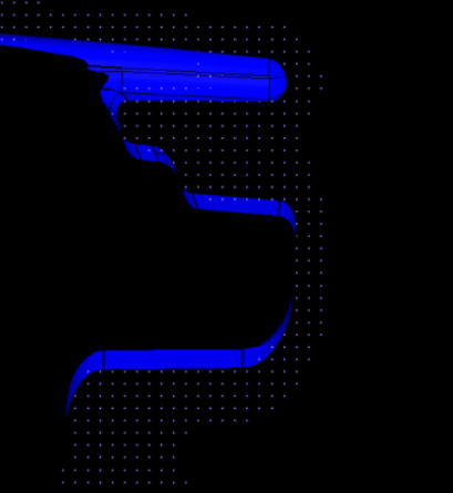

    Figure 2.
    Check External to volume to create SPH particles outside of the defined volume.
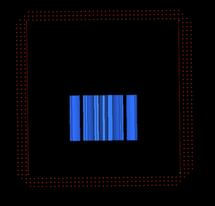

    Figure 3.
  11. Check Wall clearance to create SPH particles from the specified distance.
    Tip: This is useful when you are trying to avoid contact of SPH elements with walls at the beginning of the solver run (1st iteration) and want the solver to run smoothly.
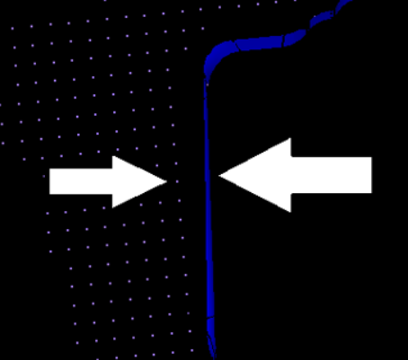

    Figure 4.
  12. Click Mesh.