Link Geometries
Description
This element defines the track link geometry. The x, y, and z axes define a local
reference frame for a track link. The x-axis is longitudinal to the driving
direction, the y-axis is lateral, and the z-axis is normal to the plane spanned by
the x- and y-axes. Keep the direction of the z coordinate as shown in the figure below.
Keep the reference coordinate system parallel to the CG coordinate system. The CG
coordinate system is defined in the MotionView model.
You can choose the location of the reference frame origin.
Note: The lateral
locations of the origin of all systems and points are in the middle of the
track-link.
For soil contact, define the contact points. The number of points depends on the shape of the link. It is recommended not to exceed three points. The maximum points allowed in the model is five. The scheme of a track-link with three typical contact points is shown in this figure. The track links with 2, 3 and 5 contact points are shown in this figure.
Parameters
- WIDTH
- (REAL)
- N_CP
- The number of contact points.
- WID_OR_MIN
- Definition of Bekker parameter b (see appendix A).
- HEIGHTi
- (REAL)
- LENGTHAi
- (REAL)
- LENGTHBi
- (REAL)
- XC, ZC
- (REAL)
- Xi, Zi
- (REAL) – X and Z components of a vector in the reference coordinate system to point i. For details, see the figure below.
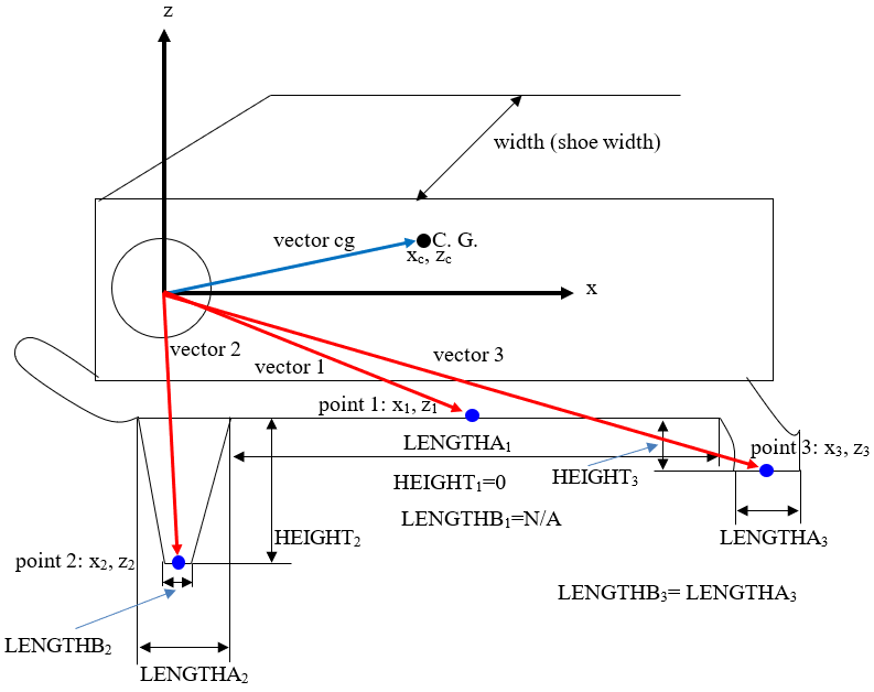
Figure 1. Scheme of a track link with three typical contact points. x, z – coordinate system of the link body. Note that the C. G. coordinate system should be parallel to the body coordinate system.
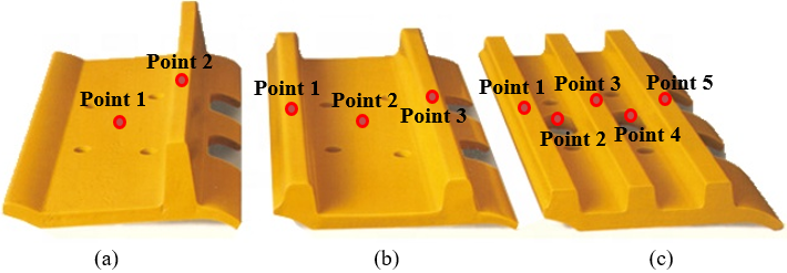
Figure 2. Track links: (a) link with one grouser and two contact points, (b) link with two grousers and three contact points, and (c), link with three grousers and five contact points.