This manual provides a detailed list and usage information regarding command statements, model statements, functions and
the Subroutine Interface available in MotionSolve.
Model ElementConstraint_CVCV defines higher pair constraint. The constraint consists of a 3D curve fixed on one body rolling and sliding on a 3D curve
fixed on a second body. The curves are required to have a unique point of contact and a common tangent at that point of
contact.
Model ElementConstraint_CVSF defines a higher pair constraint. A curve on one body slides on a surface that is fixed to a second body. The curve
is not allowed to lift off the surface.
Model ElementConstraint_Jprim is used to remove degrees of freedom between two bodies by specifying conditions in which the relative translational
or rotational motion can occur.
Model ElementConstraint_PTCV defines a higher pair constraint. A fixed point on one body slides on a curve that is fixed on a second body. The
point is not allowed to lift off the curve.
Model ElementThe Constraint_PTdCV element constrains a fixed point on a body to slide along a curve that passes through the origins of a specified
set of markers.
Model ElementThe Constraint_PTdSF element constrains a fixed point on a body to slide along a surface that passes through the origins of a specified
set of markers.
Model ElementConstraint_PTSF defines a higher pair constraint. A fixed point on one body slides on a surface that is fixed on a second body.
The point is not allowed to lift off the surface.
Model ElementConstraint_SFSF defines a higher pair constraint. The constraint consists of a surface on one body rolling and sliding on a surface
on a second body. The surfaces are required to have a unique contact point.
Model ElementThe Constraint_UserConstr element is used to specify a user defined constraint. Your constraint equations may involve the configuration as
well as velocity of the system.
Model ElementControl_Diff defines a single, first order, user-defined differential equation in MotionSolve. A single, dynamic state is associated with the differential equation. This state is integrated along with the rest of
the system states.
Model ElementControl_SISO is an abstract modeling element that defines a linear, time invariant dynamic system in the Laplace domain. SISO stands
for Single Input Single Output.
Model ElementControl_StateEqn is an abstract modeling element that defines a generic dynamic system. The dynamic system is characterized by a vector
of inputs u, a vector of dynamic states x, and a vector of outputs y. The state vector x is defined through a set of differential equations.
Model ElementForce_Beam defines a straight, massless beam of uniform cross section acting between two Reference_Markers, I and J that belong to two different bodies.
Model ElementForce_StateEqn is an abstract modeling element that combines the modeling capabilities of the Control_StateEqn and the Force_Vector_TwoBody model elements.
Model ElementThe JointInitialvel_Cyl element defines the initial velocity for a cylindrical joint element. It allows you to specify the initial velocities
for both the translational and the rotational degree of freedom.
Model ElementParam_Linear defines the solution control parameters for a linear analysis. These parameters control the types of linear analyses
to be done and the output options.
Model ElementParam_Simulation defines the solution control parameters for simulations that are associated with more than one analysis method. Exceptions
are noted.
Model ElementDefines the solution control parameters for static and quasi-static analysis, where the parameters control the accuracy
of the solution and the method to be used for solution.
Model ElementPOST_REQUEST defines an output request entity in MotionSolve. POST_REQUESTs are written to MotionSolve output files so that they may be used for plotting and signal processing by HyperGraph and HyperGraph 3D.
Model ElementReference_DeformCurve specifies a deformable curve that is made to pass through the origins of a specified set of markers, using CUBIC
spline interpolation. These markers may be on separate bodies. As the markers move in space, the curve shape is
recalculated using CUBIC spline interpolation, thereby allowing the curve to deform.
Model ElementReference_DeformSurface element specifies a deformable surface that is made to pass through the origins of a specified set of markers, using
CUBIC spline interpolation.
Model ElementReference_FlexData contains the condensed representation of the flexibility characteristics of a flexible body. The flexibility data is calculated
using a finite element solver, where the complete finite element model is available.
Model ElementA Reference_Marker defines an orthonormal, right-handed coordinate system and reference frame in MotionSolve. A Reference_Marker must belong to a body. The body can be any type: rigid, flexible, or point.
Model ElementReference_ParamCurve defines a parametric curve element. A parametric curve is defined in terms of one free parameter, u. Referring to the image below, assume a curve C is defined with respect to a coordinate system OXYZ.
Model ElementReference_ParamSurface defines a parametric surface element. A parametric surface is defined in terms of two free parameters: u and v. Referring
to the image below, assume a surface S is defined with respect to a coordinate system OXYZ.
Model ElementReference_PlantState defines a list of user-defined states used in generating a linear representation of a model about an operating point.
The linear representation is used for both eigenvalue analysis and state matrix generation.
Model ElementReference_String defines a user defined text string in MotionSolve. The string may be of any length. It must contain only printable ASCII characters.
Model ElementA Sensor_Evaluate element is always associated with one or more Sensor_Event modeling elements. When a Sensor_Event becomes "active", a Sensor_Evaluate may be optionally called to define a scalar value based on the current value of the system states. This value is not
re-evaluated until one of the parent Sensor_Event's becomes active again.
Model ElementThe Sensor_Proximity element defines a sensor that measures the minimum distance between the graphics/mesh of two bodies. The sensor tracks
the state of interference of the graphics/mesh, the length of the minimum distance, and the coordinates of
a pair of closest points. These quantities can be accessed using the PROXIMITY function for use in defining expressions or for plotting.
This manual provides a detailed list and usage information regarding command statements, model statements, functions and
the Subroutine Interface available in MotionSolve.
Element identification number (integer>0). This number is unique among
all Force_Bushing elements and uniquely identifies
the element.
label
The name of the Force_Bushing element.
i_marker_id
Specifies the Reference_Marker at which the force is
applied. This is designated as the point of application of the
force.
j_marker_id
Specifies the Reference_Marker at which the reaction
force and moment are applied. This is designated as the point of
reaction of the force.
kxkykz
ktxktyktz
These define the diagonal entries for a 6x6 stiffness matrix that is
used to calculate the spring force for
Field_Bushing. All stiffness values must be
non-negative.
cxcycz
ctxctyctz
These define the diagonal entries for a 6x6 damping matrix that is used
to calculate the damping force for Field_Bushing.
All damping values must be non-negative.
preload_xpreload_ypreload_z
preload_txpreload_typreload_tz
These define the pre-loads in the Force_Bushing
element. In other words, the forces at I when there is deformation.
The force and torque components are measured in the J coordinate
system. The data is optional. Their default values are 0.
Example
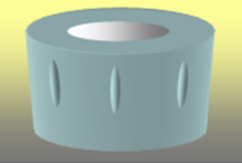
The example demonstrates the definition of a bushing element commonly used in
automotive suspensions such as bump stops for shocks and struts. The image below
is an illustration of such a bushing.
Figure 1. A Bump Stop Bushing in an Automotive Suspension
The Force_Bushing definition for such a bushing could be:
The force and torque consist of three major effects:
a spring force, a damping force, and a pre-load vector.
The spring force is defined by the product of the stiffness matrix
and the relative displacement between the I
and JReference_Markers.
The damping force is defined by the product of the damping matrix
and the relative velocity between the I and
JReference_Markers.
A preload vector can also be added to the spring and damping
forces. The six components (three forces and three moments) are
defined in the coordinate system of the JReference_Marker.
Force_Bushing elements are used
as compliant connectors in mechanical systems. They are typically used to
reduce vibration and noise, absorb shock, and accommodate
misalignments.
kx, ky and
kz have units of force per unit length.
cx, cy and cz
have units of force per unit length per unit time. ktx,
kty, ktz have units of torque
units per radian. ctx, cty,
ctz have units of torque units per radian per unit
time. The actual units are governed by what are defined for the entire
model.
Two of the three angular deflections, rotation about
X, rotation about Y and rotation about Z, must remain small at all times.
The rotation angles lose physical significance otherwise. Small means <
10 degrees.
i_marker_id is designated as the
point of application of the Force_Field.
j_marker_id is the point of reaction.
The forces acting at the I and
J markers are equal and opposite. Since there
usually is a separation between J and
I and the force does not act along the separation
vector, the torque acting on the I marker is not the
same as the torque acting on the J marker. This is shown
in Figure 2 below.
Figure 2.
The sign convention for the forces and torques is as
follows:
A positive force tends to repel the I and
JReference_Markers. A negative force tends to
attract the I and JReference_Markers.
A positive torque tends to rotate the IReference_Marker in a counterclockwise
direction, relative to the J Reference_Marker.
Thus, a positive value of TX tends to increase
the value of included angle between the x-axes of Markers I and
J.
Force_Bushing is a linear
element. If you wish to define a nonlinear force element, then use either
the Force_Field or the
Force_Vector_TwoBody modeling element.
Force_Bushing does not model
cross-coupling effects. Its stiffness and damping matrices are diagonal. If
cross-coupling effects are important, use Force_Field or
Force_Vector_TwoBody.
Force_Bushing can act on all
bodies: Body_Rigid, Body_Flexible,
and Body_Point.
The MotionSolve
bushing implementation is slightly different from the one in Adams. In most
cases, they yield the same results; however if the bushing undergoes 3-D
deformation, the results can be somewhat different. Both products
approximate large angles, but slight differently. Hence the results will be
different.