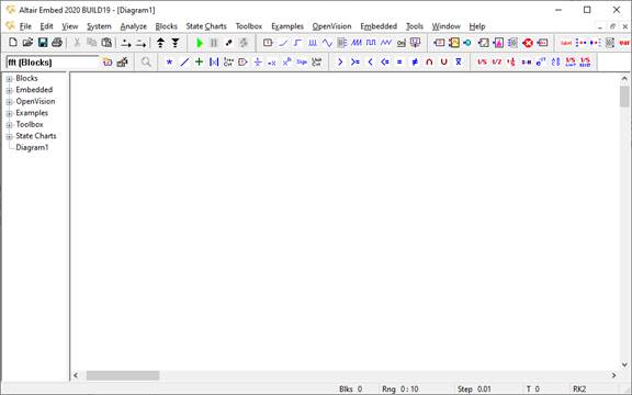
Start Embed.
An empty diagram appears named Diagram1.
To construct the second-order system, you will use a step block, two integrator blocks, and a plot block.
1. Choose Blocks > Signal Producer and click step.

2. The Blocks menu disappears, and the pointer appears with a marquee attached to it.

3. Move the pointer to the work area and click to add the step block.

4. Repeat these steps to add two integrator blocks and a plot block. The integrator block is under Blocks > Integration, and the plot block is under Blocks > Signal Consumer.

You can also use the toolbar or Browser windowpane to add blocks to a diagram. See Inserting blocks for all methods of populating a diagram.
By connecting blocks, you can pass signal values, or data, from one block to another. You connect blocks by creating a wire between the input and output connector tabs on blocks.

To make a connection
1. Point to the output tab on the step block. The pointer turns into an upward pointing arrow when it is over the tab.

2. Drag the pointer to the input tab on the integrator block. When you release the mouse button, the connection is completed.

When all the connections are complete, the diagram looks like this:

To undo a connection
1. Point to the input tab on the block and drag the pointer away from the block.
2. When you release the mouse button, the connection disappears.
Moving blocks is one of the more common editing actions you perform on blocks. As you build your diagram, you will often have to move blocks around the work area. When blocks are connected, you can move them around the work area without breaking their connections.
To move blocks
1. Position the pointer over the block and hold down the mouse button.
2. Drag the mouse to reposition the block.

Most blocks have parameters that allow you to set attributes specific to the block.
To set block parameters
•Right-click the mouse over the step block to display the Properties dialog box.
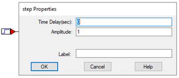
For this example, no changes are required; however, it is worth noting that you can control the strength of the output signal and the time to delay before calculating the output signal. You can also create a block label that appears below the block when you activate View > Block Labels.
Before starting a simulation, you can set the parameters of the simulation, including the integration algorithm and duration of the simulation.
To specify simulation parameters
1. Choose System > System Properties.
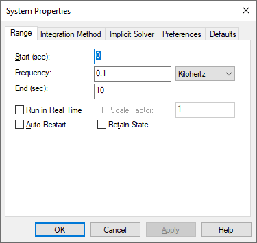
2. In the End box, enter 20 and click OK.
Embed sets the simulation stop time to 20 sec and closes the dialog box.
The diagram is now ready to be simulated. To start the simulation, choose System > Go.

The simulation runs until it reaches the specified end time. The plot block displays the simulation results for x2/2 from 0 to 20 sec.
When you create a new diagram or edit an existing diagram, the work you do is saved in a temporary buffer. To make the changes permanent, use one of the File > Save commands.
You can tell if your changes have not been saved if there is an asterisk after the diagram name in the title bar.
When you are ready to end your Embed session, click the File > Exit command.