Adding a Cutplane

Create a sectional view of the model by using a cut plane to show internal details that would otherwise be hidden. Multiple cutplanes are supported.

  1. On the 3D View contextual tabs set, on the Display tab, in the Display group, click the  Cutplanes icon.
  2. Click the Plane definition tab.


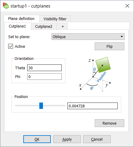
    Figure 1. The Cutplanes dialog, Plane definition tab.
    1. [Optional] To create additional, click +.
      Note: Click Remove to delete the cutplane.
    2. In the Set to plane drop-down list, select one of the following for the orientation of the cutplane:
      • Global YZ
      • Global XZ
      • Global XY
      • Oblique
        • In the Theta field, specify the theta angle in degrees.
        • In the Phi field, specify the phi angle in degrees.
    3. [Optional] Click the Flip to alternate the normal direction of the cutplane, which in turn determines which side of the plane is hidden.
    4. Under Position, use the slider to place the cutplane at a specific location.

By default, everything in the model is affected by the cutplane. Entities that should be left uncut, can be specified.

  1. [Optional] Click the Visibility filter tab.


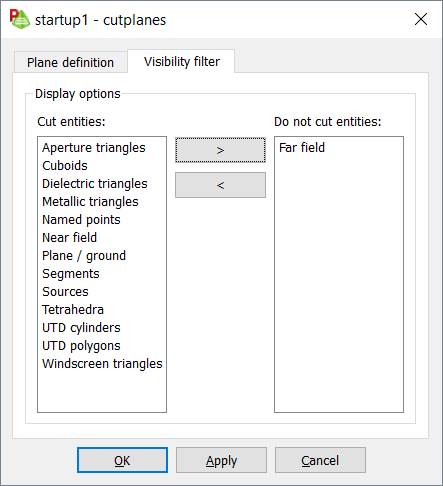
    Figure 2. The Cutplanes dialog, Visibility filter tab.
    1. To prevent an entity from being cut, in the Cut entities panel, select the entity and click >.
  2. Click OK to define the cutplane and close the dialog.