Electrical description
Introduction
The fourth stage corresponds to the electrical description of the conductors. That means the description of the electric environment (electrical scheme), as well as the electric connections among the different conductors.
Application
The electric circuit described depends on the selected application:
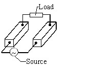
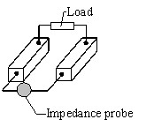
Supplied conductors or Conductors impedance.
|
Supplied conductors application |
Conductors impedance application |
|---|---|
|
It is necessary to define at least one supply source and possibly passive components or loads |
It is necessary to define at least one impedance probe and possibly passive components or loads |
|
|
Electrical circuit
The electrical circuit is made of:
- unidirectional and bidirectional conductors previously described
- complementary components (sources, passive component, probe)
- connections between these circuit components (connections are carried out via the terminals)
Whatever the quantities seeked are (currents or equivalent impedances), it is necessary to have closed current loops.
Components
The available components for the two Flux PEEC computation types are presented in the table below.
| Supplied conductors application | Conductors impedance application |
|---|---|
|
|
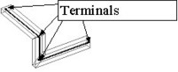
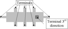
Terminals
Terminals, defined with respect to the conductors, allow connections. They are presented in the table below.
|
Unidirectional conductor: (the terminals are automatically created with the conductor geometry) |
||
|---|---|---|
| geometric tube conductor | a tube point = a terminal |
|
| CAD geometry conductor | input / output faces must be defined by the user |
|
|
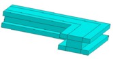
Bidirectional conductor: (the terminals are created after the conductor geometry) |
|
|---|---|
| Points or faces defined by the user |
|
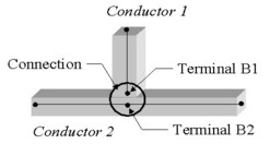
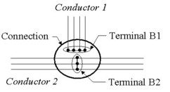
Connections
The connections between the conductors are carried out via the terminals.
 |
 |