Assimilation conductor mode: physical description
Introduction
In assimilation conductor mode, the physical description of uni- and bi- directional conductors is the responsibility of the user, as well as the description of the terminals for the bidirectional conductors.
Physical characteristics
An assimilation conductor is characterized by:
- a type of conductor (uni- or bi- directional conductor)
- a material (with its resistivity)
- information related to the meshing (type of mesh, density)
Uni- and bi- directional conductor: reminder
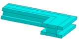
It is possible to model with Flux PEEC two types of conductors: the uni- and bi- directional conductors, as presented in the table below.
| A unidirectional conductor is a … | |
|---|---|
|
|
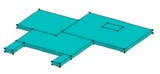
| A bidirectional conductor is a … | |
|---|---|
|
|
Materials
The materials are electro conductive materials, nonmagnetic, characterized by their resistivity in Ω.m.
The characteristics of available materials are presented in the § Choice and definition of the application. The user can create other materials.
Types of mesh
In order to mesh the uni- or bi-directional assimilation conductors, several types of discretization of the conductors are proposed, as presented in the table below.
| Unidirectional conductor (1D) | Bidirectional conductor (2D) |
|---|---|
meshing of the cross-section perpendicular to the direction of the
current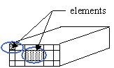 |
meshing of the plane where current flows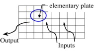 |
|
uniform meshing The same technique used to uniformly mesh tube conductors with full cross-sections is applied. 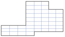 |
uniform meshing The rectangle including the plate is meshed uniformly on the basis of numbers n and m PEEC elements that the user has previously indicated. 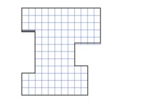 At the borders this can lead:
|
| automatic meshing according to the reference frequency The technique used to automatically mesh tube conductors with variously-shaped full cross-sections is applied. 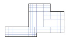 |
automatic meshing according to the frequency This feature is not implemented in version 2.1 of Flux PEEC; it is planned for future releases. |
Terminals
The terminals of the assimilated unidirectional conductors are created automatically with the creation of the conductor. They correspond to the faces of entry and exit of the current.
The terminals of the assimilated bidirectional conductors are created by the user.
Summary
The table below summarizes the different phases of the general process for the physical description of the conductors.
| Stage | Description |
|---|---|
| 1 | Creation of the materials |
| 2 | Creation of the unidirectional / bidirectional conductors
|
| 3 | Creation of a ground plane (possibly) |
| 4 |
Creation of the terminals (only for bidirectional conductors) |