Orienting and assigning terminals to coil conductor regions in 3D periodical domains
Introduction
This chapter explains how to assign a coil conductor region (without losses,with losses and simplified geometrical description or with losses and detailed geometrical description) to volumes and discusses the procedure required to create its electric terminals and define the current sense when a periodicity exists in a Flux 3D project.
When the Flux 3D project contains a periodicity, the orientation procedure is influenced by the presence of a symmetry condition imposing a tangent magnetic field at the boundaries of the FEM domain (allowing the representation of only a part of the device) and thus deserves a special attention from the user.
In the following sections, the example of a three-phase rotating machine winding will be adopted to explain:
- how to assign a coil conductor region to volumes when they are cut by the periodicity planes;
- how to orient the current sense of the coil conductor regions by assigning their terminals coherently, depending on the existence of a tangent field symmetry and on the type of periodicity (even/cyclic or odd/anti-cyclic) in the project.
Example of a rotating machine
| PHASE_A_1 | PHASE_B_1 | PHASE_C_1 |
| PHASE_A_2 | PHASE_B_2 | PHASE_C_2 |
| PHASE_A_3 | PHASE_B_3 | PHASE_C_3 |
| PHASE_A_4 | PHASE_B_4 | PHASE_C_4 |
| PHASE_A_5 | PHASE_B_5 | PHASE_C_5 |
| 3-phase windings of a rotating machine. There are three phases: phase A (orange), phase B (purple) and phase C (green) and five regions per phase | |
| A quarter of the device is described due to a periodicity | Half a quarter of the device is described due to a periodicity and a Tangent magnetic fields symmetry |
 |
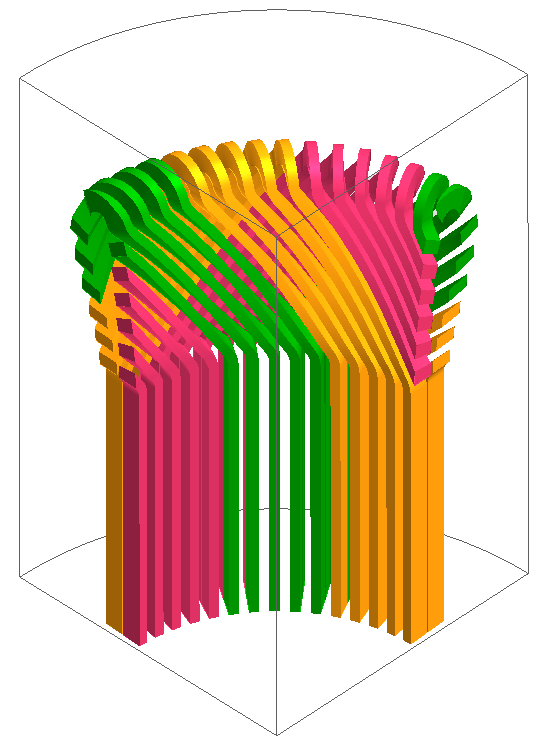 |
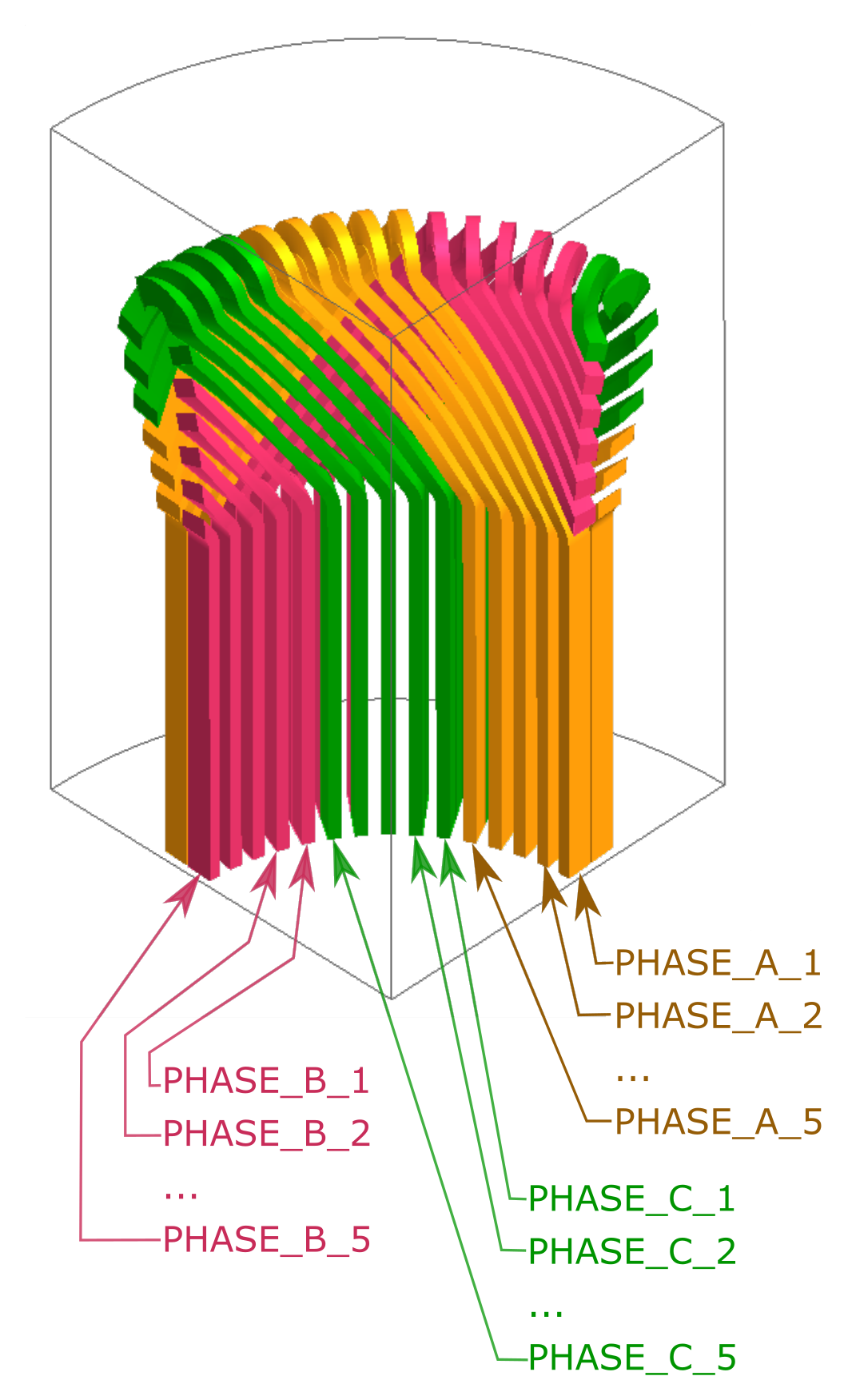
Figure 1. Names of coil conductor regions of the rotating machine
How to assign a coil conductor region to volumes when it is cut by the periodicity planes?
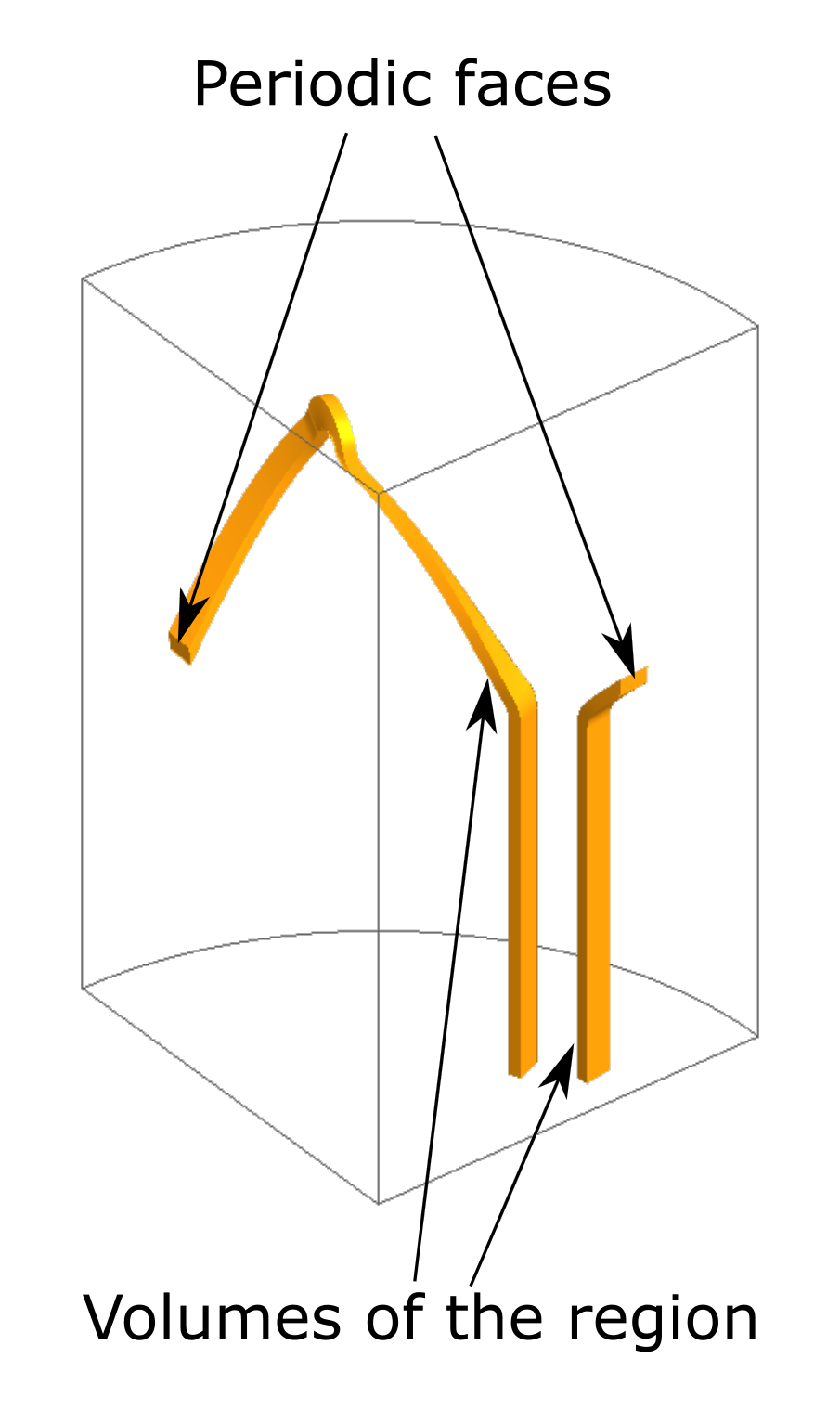
The volumes of a coil conductor region must correspond to a whole coil. When the periodicity planes cut such a region, its volumes are split into two separate groups of contiguous volumes. The two groups are linked by their periodic faces, as described in the following figures.
This section explains how to assign a coil conductor region to volumes when it is cut by the periodicity planes by one of the following commands:
- Assign regions to volumes (completion mode)
- Assign regions to volumes (modification mode)
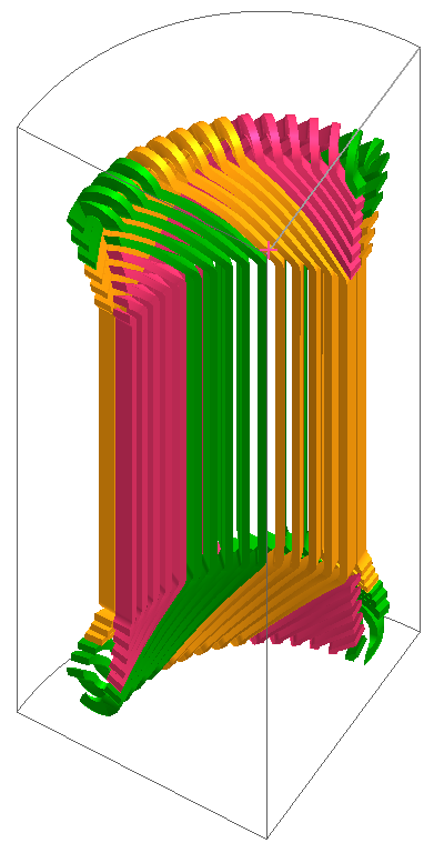
| Region PHASE_A_1. It consists of one group of contiguous volumes | Region PHASE_A_4. It is split into two separate groups of contiguous volumes, because it is cut by periodicity planes. | |
| With a symmetry plane |
 |
 |
| Without any symmetry plane |
 |
 |
| Selection of the volumes of region PHASE_A_4 cut by periodicity planes | |
| Real coil displayed by clicking on the icon Display or not the full device | Volumes to select for coil conductor region cut by the periodicity planes. |
 |
  |
How to define the electric terminals?
- Orient wires of coil conductor region (completion mode)
- Orient wires of coil conductor region (modify mode)
- with an even/cyclic periodicity,
- with an odd/anti-cyclic periodicity,
- with an even/cyclic periodicity and a Tangent magnetic fields symmetry,
- with an odd/anti-cyclic periodicity and a Tangent magnetic fields symmetry.
These four cases are addressed in the following subsections.
Cyclic or anticyclic periodicity:
- Select internal terminals,
- Select the faces of the input / output terminal intersecting the coil,
- Select the line indicating the side of the input terminal and the positive current direction.
| Selection of the faces and line of the input terminal of regions for cyclic periodicity | |
| Configuration | Region PHASE_A_1 |
|
Cyclic periodicity
PHASE_A_1 PHASE_A_2
|
 |
| Configuration | Region PHASE_A_4 |
|
Cyclic periodicity
PHASE_A_3 PHASE_A_4 PHASE_A_5 PHASE_B_1 PHASE_B_2 PHASE_B_3 PHASE_B_4 PHASE_B_5 |
 |
| Configuration | Region PHASE_C_1 |
Cyclic periodicity
PHASE_C_1 PHASE_C_2 PHASE_C_3 PHASE_C_4 PHASE_C_5 |
 |
| Selection of the faces and line of the input terminal of regions for anticyclic periodicity | |
| Configuration | Region PHASE_A_1 |
|
Anticyclic periodicity
PHASE_A_1 PHASE_A_2
|
 |
| Configuration | Region PHASE_A_4 |
|
Anticyclic periodicity
PHASE_A_3 PHASE_A_4 PHASE_A_5 PHASE_B_1 PHASE_B_2 PHASE_B_3 PHASE_B_4 PHASE_B_5 |
 |
| Configuration | Region PHASE_C_1 |
Anticyclic periodicity
PHASE_C_1 PHASE_C_2 PHASE_C_3 PHASE_C_4 PHASE_C_5 |
 |
Cyclic periodicity and “Tangent magnetic fields” symmetry:
- Select external terminals,
- Select the faces of the input terminal. They are located on the symmetry plane,
- Select the faces of the output terminal. They are located on the symmetry plane.
|
Selection of the faces of the terminal of regions (view from underneath) |
|
| Configuration | Region PHASE_A_1 |
|
PHASE_A_1 PHASE_A_2
|
 |
| Configuration | Region PHASE_A_4 |
|
PHASE_A_3 PHASE_A_4 PHASE_A_5 PHASE_B_1 PHASE_B_2 PHASE_B_3 PHASE_B_4 PHASE_B_5 |
 |
| Configuration | Region PHASE_C_1 |
PHASE_C_1 PHASE_C_2 PHASE_C_3 PHASE_C_4 PHASE_C_5 |
 |
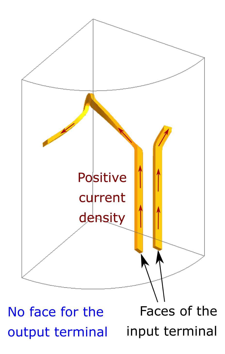
Anticyclic periodicity and “Tangent magnetic fields” symmetry:
When there is an anticyclic periodicity and a Tangent magnetic fields symmetry, the faces of the terminals to select are those located on the symmetry plane.
- If the region is not cut by the periodicity planes, for regions PHASE_A_1
and PHASE_A_2:
- Select external terminals,
- Select the faces of the input terminal. They are located on the
symmetry plane,
- Select the faces of the output terminal. They are located on the symmetry plane.
- If the region is cut by the periodicity planes and the positive current
enters the region on the symmetry plane, for regions PHASE_A_3, PHASE_A_4,
PHASE_A_5, PHASE_B_1, PHASE_B_2, PHASE_B_3, PHASE_B_4 and PHASE_B_5:
- Select external terminals,
- Select the faces of the input terminal. They are located on the symmetry plane,
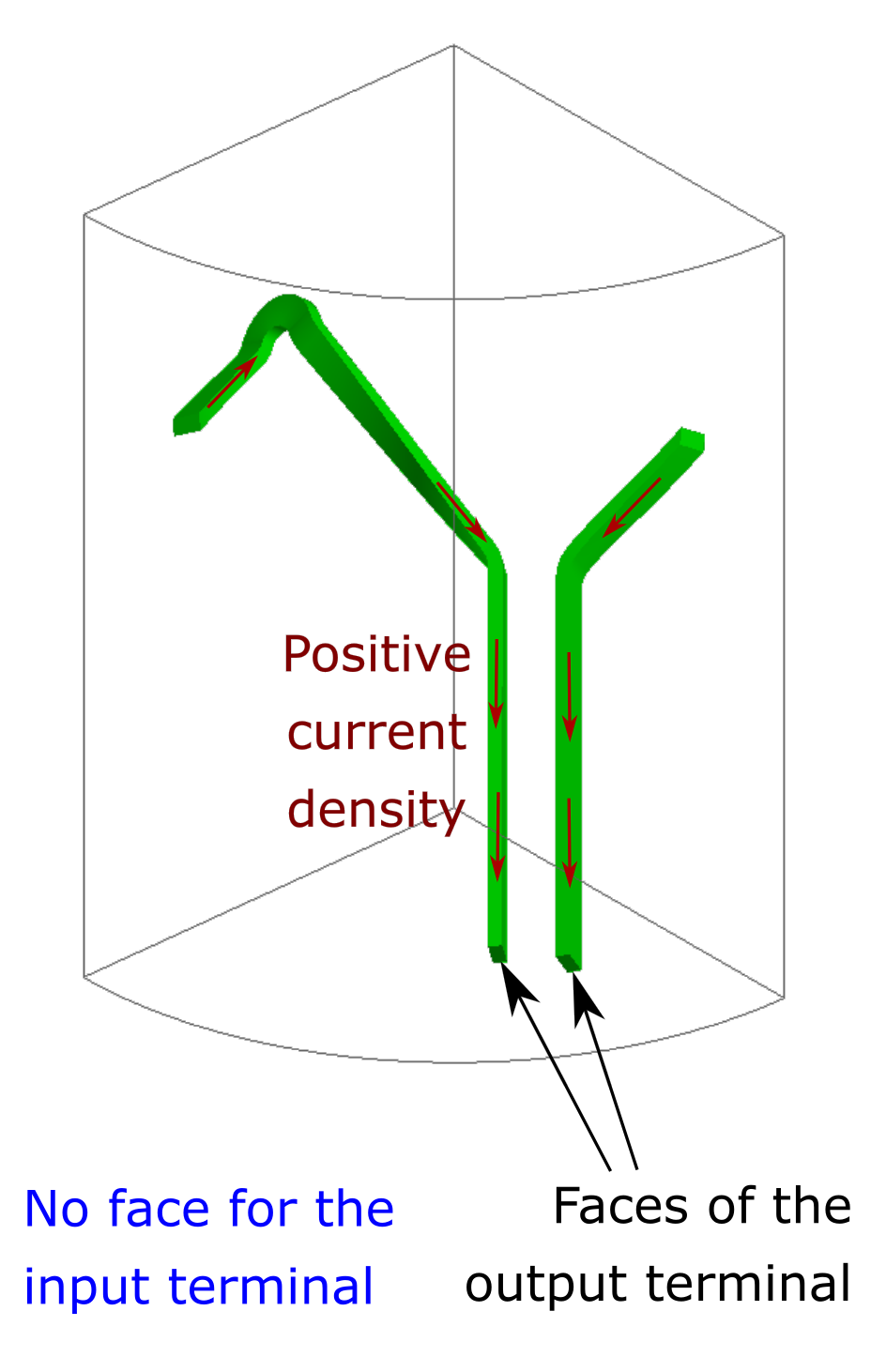
- Select no face for the output terminal.
- If the region is cut by the periodicity planes and the positive current
comes out of the region on the symmetry plane, for regions PHASE_C_1,
PHASE_C_2, PHASE_C_3, PHASE_C_4, PHASE_C_5:
- Select external terminals,
- Select no face for the input terminal,
- Select the faces of the output terminal. They are located on the symmetry plane.
|
Selection of the faces of the terminals of regions (view from underneath) |
|
| Configuration of regions | Region PHASE_A_1 |
|
PHASE_A_1 PHASE_A_2
|
 |
PHASE_A_3 PHASE_A_4 PHASE_A_5 PHASE_B_1 PHASE_B_2 PHASE_B_3 PHASE_B_4 PHASE_B_5 |
 |
PHASE_C_1 PHASE_C_2 PHASE_C_3 PHASE_C_4 PHASE_C_5 |
 |
Alternative approach to define the electric terminals in projects without a physical symmetry
Under certain circumstances, coil conductor regions reuniting the following characteresitics may exist in a Flux project:
- the coil conductor region is cut by the periodicity planes;
- the coil conductor region does not have internal faces that could be assigned to an internal terminal;
- the coil conductor region is not cut by a symmetry plane enforcing the physical condition Tangential magnetic fields, normal electric fields.
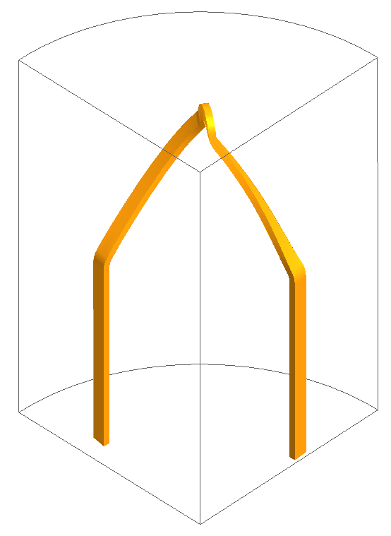
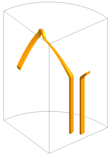
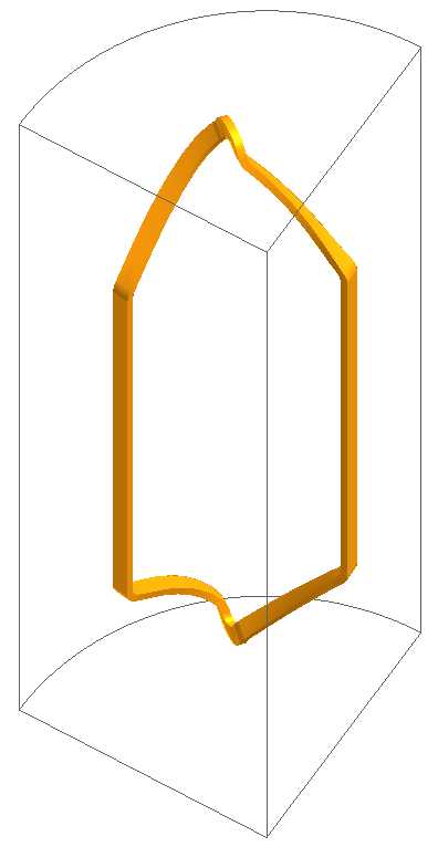
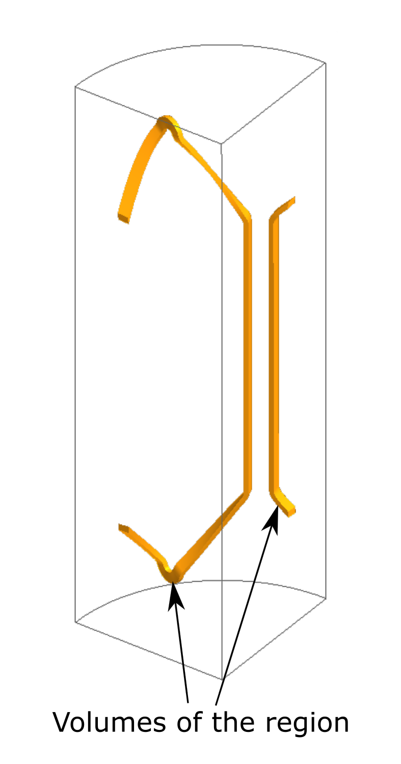
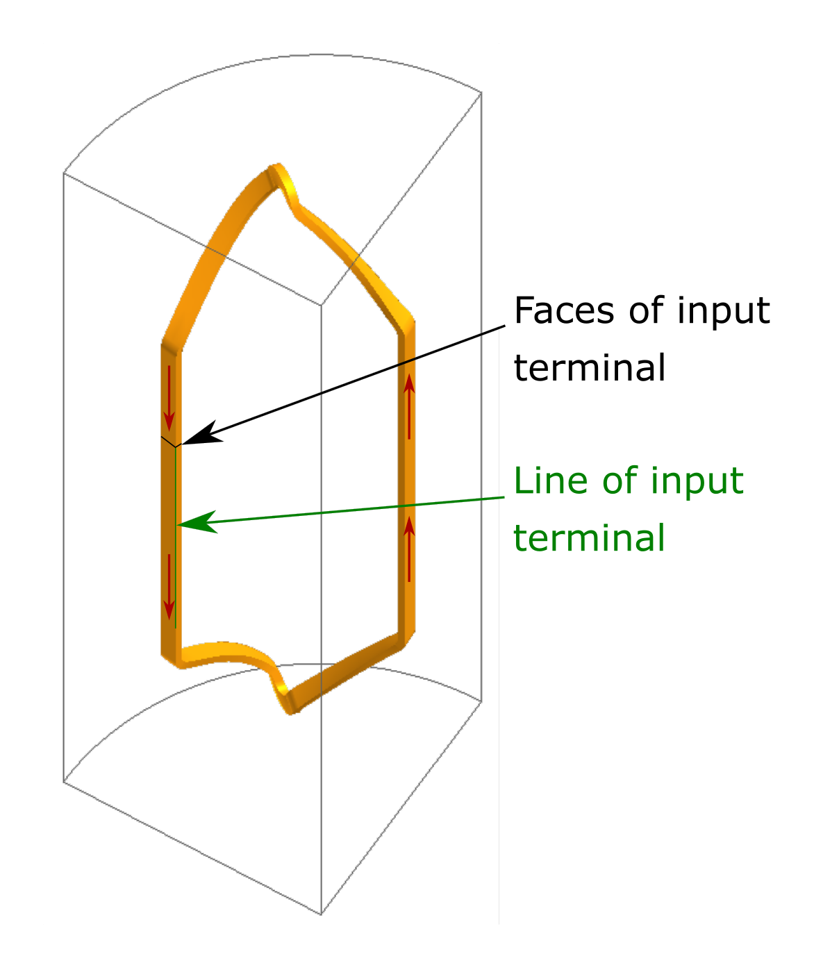
An example of such a coil conductor region is given by the ring-shaped conductor shown below (and by the coil conductor region PHASE_C_1 in the rotating machine example considered above as well). In such cases, it is easier to create the required electric terminal on the periodicity planes, and the procedure depends on the periodicity type. These two possibilities are covered in the next two paragraphs.
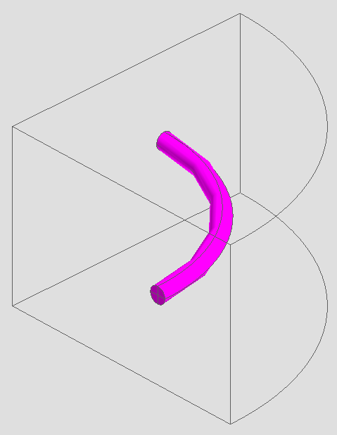 Figure 2. Example of a ring-shape coil conductor region in a FEM domain with a
90o periodicity.
Figure 2. Example of a ring-shape coil conductor region in a FEM domain with a
90o periodicity.Cyclic periodicity
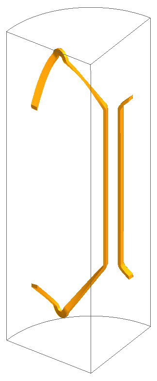
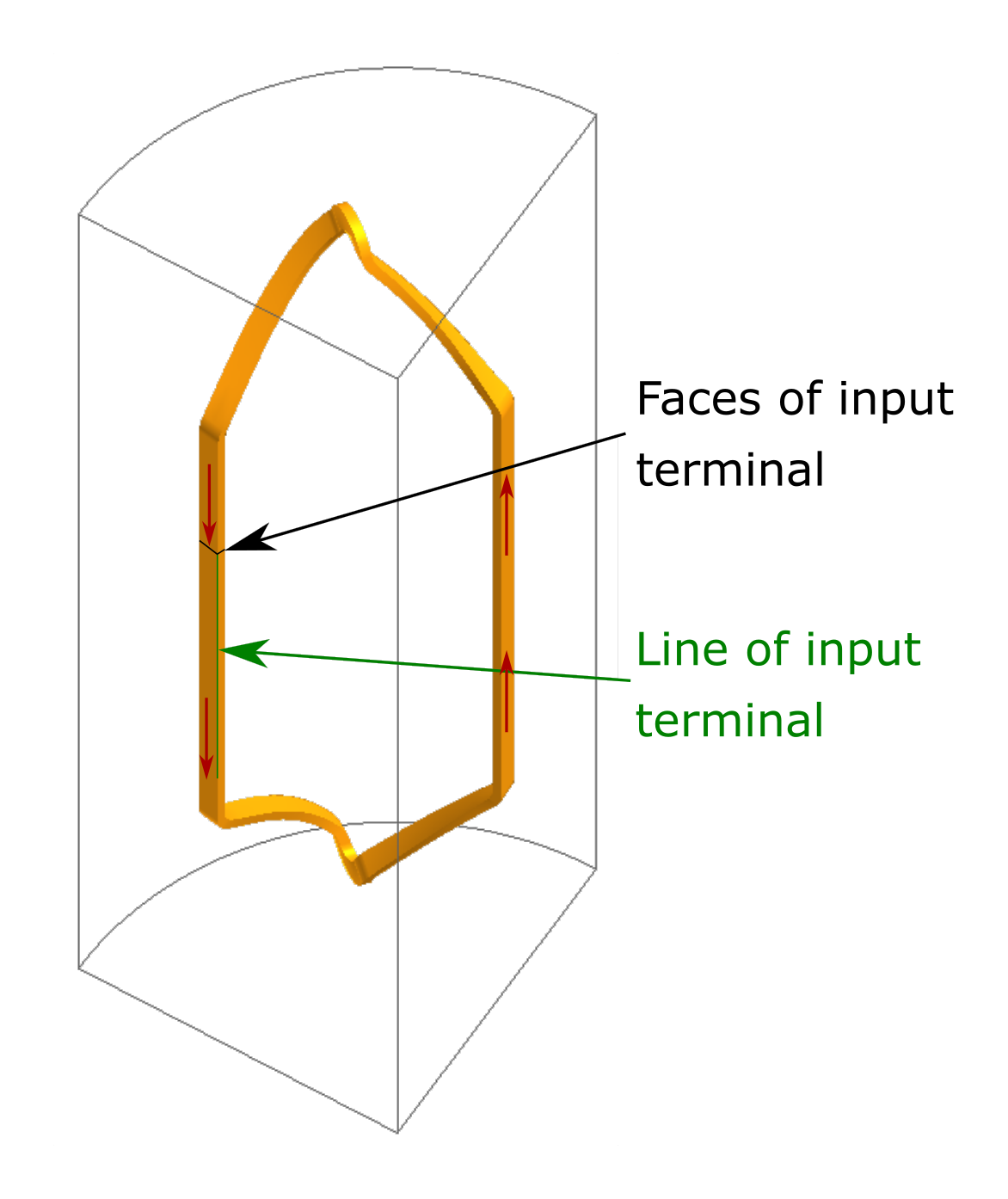
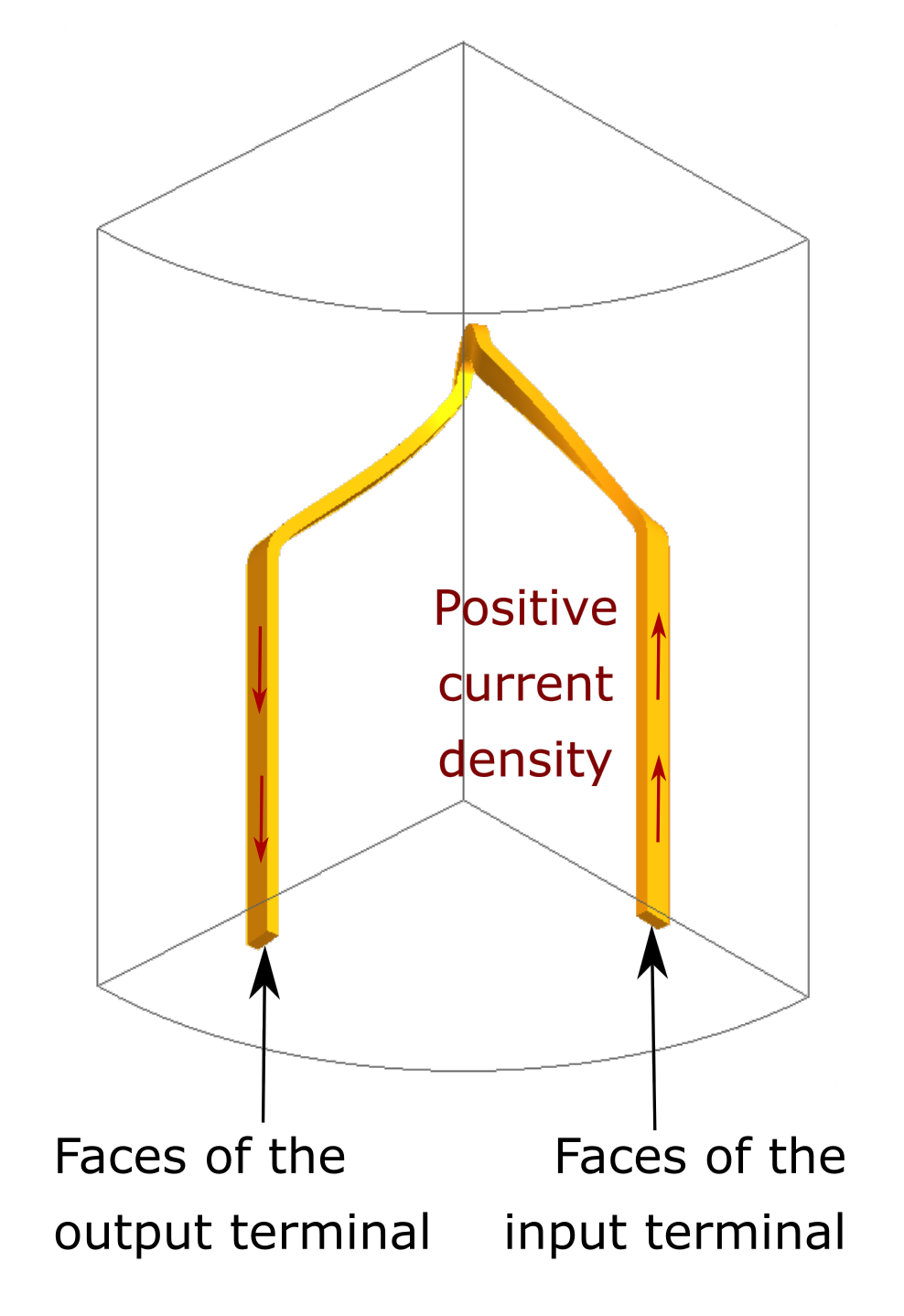
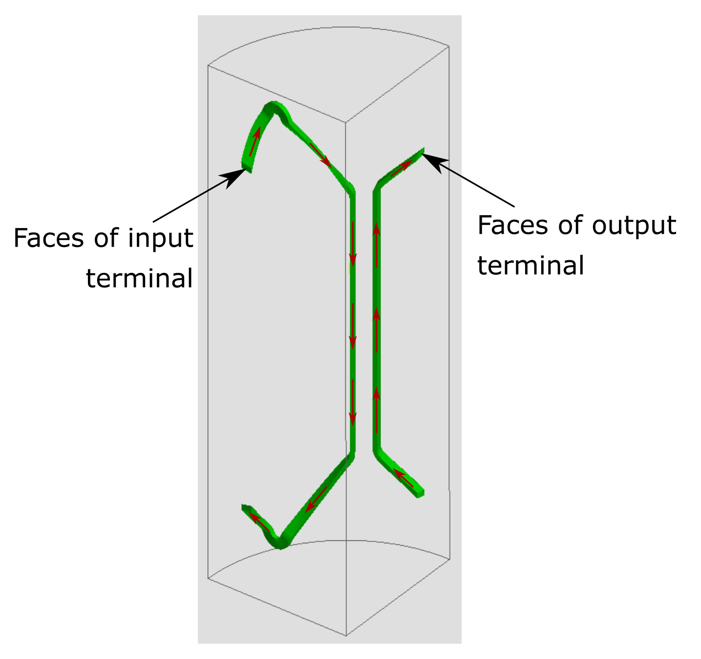
When the project has a cyclic periodicity, there are no symmetries exists and the region is cut by the periodicity planes, the faces the terminals to be selected are those located on the periodicity planes.
- select external terminals;
- select the faces of the input terminal accordingly with orientation of the current in the coil conductor region. These faces are located on a periodicity plane;
- select the faces of the output terminal. They are located on the other periodicity plane.
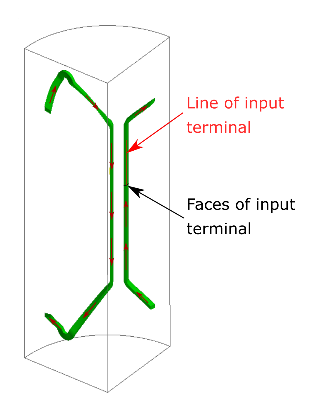
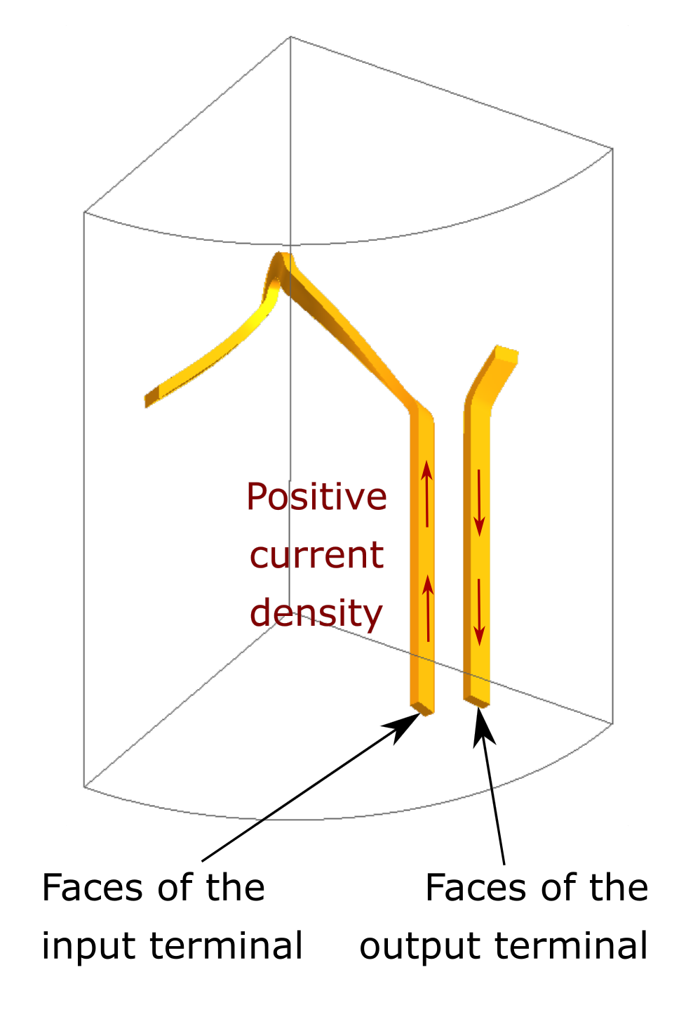
| Selection of the faces representing the terminals of a coil conductor region with a cyclic periodicity. | |
|---|---|
| Configuration | Selection of the faces |
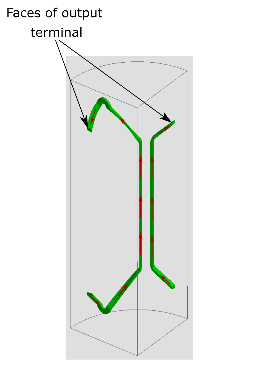
| First approach with upper terminals |
 |
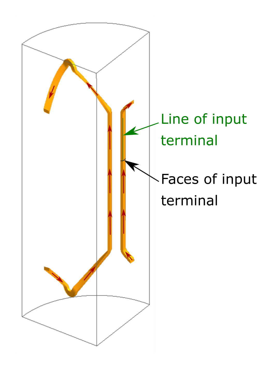
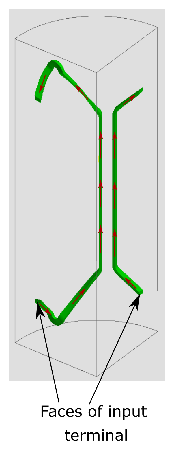
| Second approach with lower terminals |
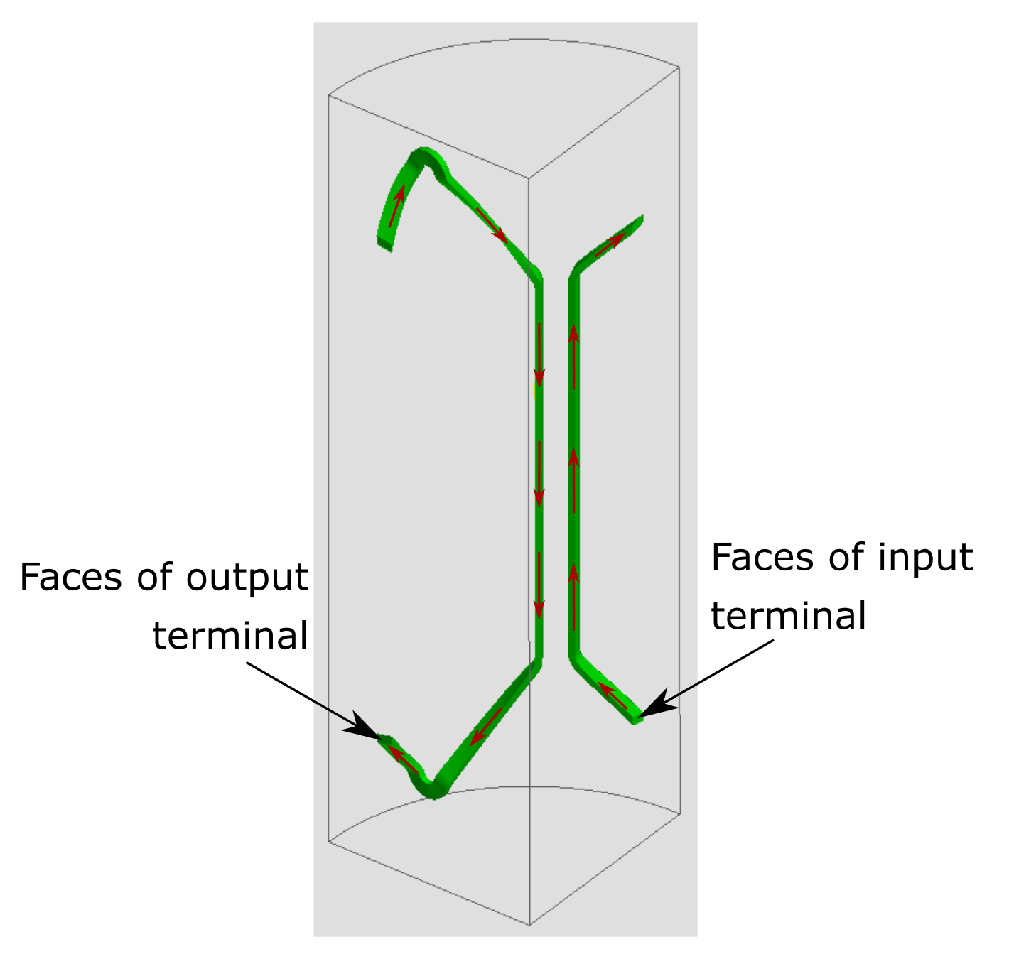 |
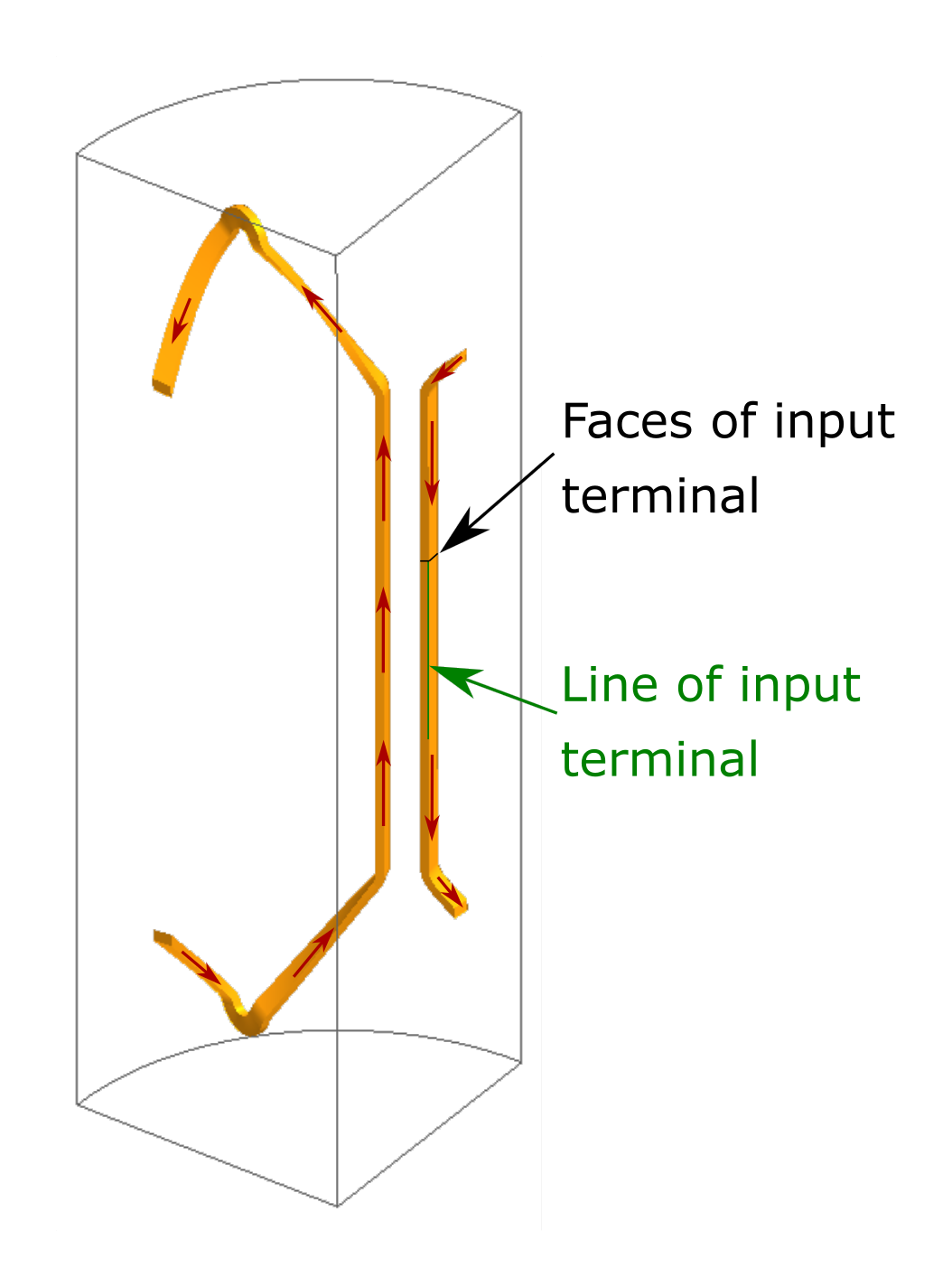
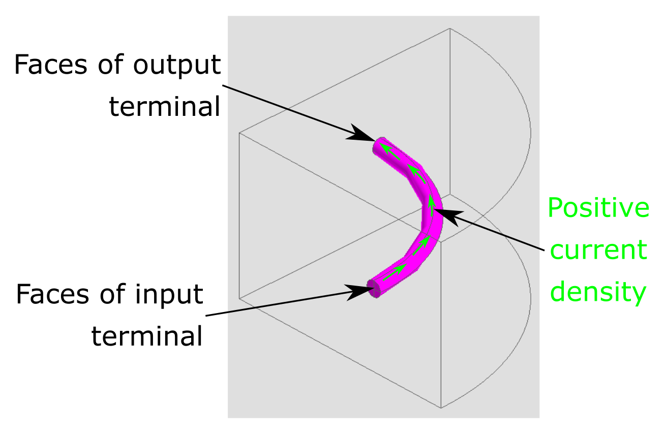 Figure 3. Selection of the faces representing the terminals of a ring-shaped coil conductor
region with a cyclic periodicity.
Figure 3. Selection of the faces representing the terminals of a ring-shaped coil conductor
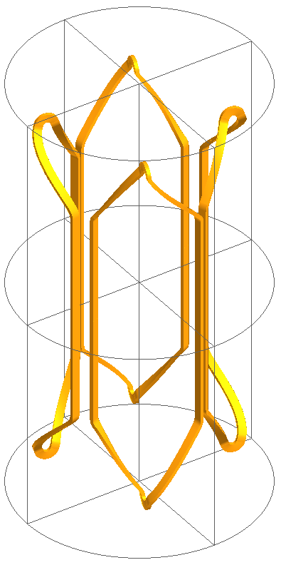
region with a cyclic periodicity.Anticyclic periodicity
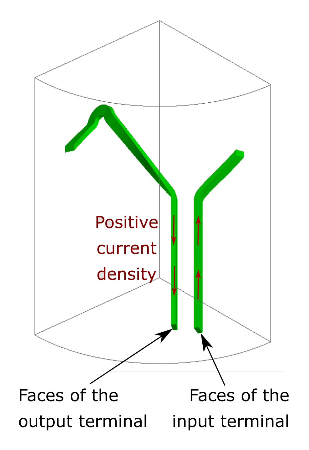
When the project has an anticyclic periodicity, there are no symmetries and the region is cut by the periodicity planes, the faces of the terminals to be selected are those located on the periodicity planes as well.
- Select external terminals.
- Accordingly with the orientation of the current in the coil conductor region, either select the faces belonging to the input terminal or the faces belonging to the ouptut terminal. In both situations they are located on the two periodicity planes.
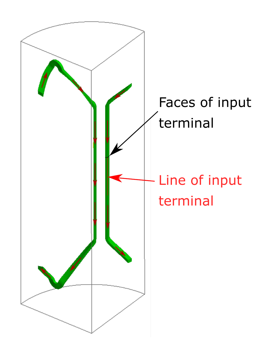
| Selection of the faces representing the terminals of a coil conductor region with an anticyclic periodicity. | |
|---|---|
| Configuration | Selection of the faces |
| First approach with upper terminals |
 |
| Second approach with lower terminals |
 |