Links between the finite element domain and the electric circuit: concepts of geometric and electric terminals
Reminder
The coupling field-circuit is carried out by means of stranded coil conductors and/or solid conductors.
These conductors are represented twice:
- once in the electric circuit:
- components of stranded coil conductor type
- components of solid conductor type
- once in the finite elements (FE) domain:
- regions of coil conductor or non meshed coil type
- regions of solid conductor type
Geometric terminal
In the finite elements domain, the conductor is represented by a volume region.
The conductor ends, corresponding to the supplies of current, are called geometric terminals.
Example :
The geometric terminals of the REG_B1 and REG_M2 conductors are the input/output faces presented in the next figure.

Name of geometric terminals: The geometric terminals have not any name in Flux.
Electric terminal
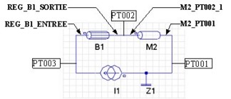
In the electric circuit, the conductor is represented by an electric component.
The conductor ends, corresponding to the supplies of current, are called electric terminals .
Example :
The electric terminals of the B1 and M2 conductors are the terminals presented in the next figure.
Name of electric terminals:
- coil conductor: NAME_REG_VOL_INPUT / NAME_REG_VOL_OUTPUT
- solid conductor: NAME_COMPONENT_PT00i (PT00i = i equipotential point)
Links
The user must link the regions of the finite elements domain to the corresponding components in the electric circuit.
The links, presented in the table below, are plurivocal. Several regions can be linked to a component (reciprocal is not true).
| FE domain |
|
Electric circuit |
|---|---|---|
| Volume regions | FE coupling component | |
|
coil conductor non meshed coil |
|
stranded coil conductor |
| solid conductor |
|
solid conductor |
… for the coil conductors
With regard to the coil conductors, links
(![]() ) are carried out in two levels (via the regions/components
and via the geometric/electric terminals), as presented in the table below.
) are carried out in two levels (via the regions/components
and via the geometric/electric terminals), as presented in the table below.
Practically, the user carries out the two following operations:
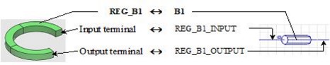
- he links a B1 component to the REG_B1 region
- he orients REG_B1 volume region (definition of the input/output terminals)
By orienting the volume region, the user defines the REG_B1_INPUT, REG_B1_OUTPUT component terminals and orients them in the circuit.
By definition, the (geometric) input terminal corresponds to the (electric) terminal indicated by a square symbol.
… for the solid conductors
With regard to the solid conductors, the
(![]() ) links are carried
out on only one level (via the geometric/electric terminals), as presented in the table
below.
) links are carried
out on only one level (via the geometric/electric terminals), as presented in the table
below.
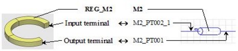
Practically, the electric terminals are automatically created at the time of the circuit importation in the Flux project. Thus the user carries out the following operation:
- he defines a geometric terminal for each electric terminal of the M2 component (M2_PT002_1, M2_PT001)