Parameterization
Introduction
The parameterization of the geometry is one of the strong points of the geometry building module.
It is possible to parameterize:
- dimensions of workpieces
- relative displacements of pieces (variable air-gap…).
Parameterization tools
A geometrical object can be parameterized:
- on one hand, using the geometrical parameters,
- on the other hand, using the local coordinate systems (coordinate systems defined with respect to a reference coordinate system).
These concepts are presented in the example below.
Example
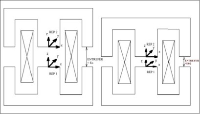
The example refers to the study of a contactor, concerning the force acting on the moving part for various values of the air-gap.
The fixed part is defined in a local coordinate system REP1 of center (0, 0, 0), and the moving part in a local coordinate system REP2 of center (0, 0, AIR-GAP). AIR-GAP is a parameter whose value is equal to the air-gap thickness.
To study various positions of the moving part, and thus various values of the air-gap, it is enough to modify the value of the corresponding parameter (AIR-GAP) and to treat the corresponding case.
Principle and limits
Each time that a geometrical entity is modified, all the entities depending on this geometrical entity are automatically reevaluated through the database tools.
Modifying a parameter or a coordinate system entails the modification of the points, then of the lines, and then of the faces and volumes that are attached to this parameter.
Important: the coherence of the topology (intersection, superposition…) is not verified by the software. This verification is a user task.
In the previous example, a null value of the AIR-GAP parameter leads to a modification of the geometry topology that can not be realized due to superposed points and lines. This limit case cannot be treated by parameterization.
Advice
Defining local coordinate systems using a first coordinate system allows the user to define a "father coordinate system", to which is attached a series of "children coordinate systems". By modifying the "father coordinate system" the user will modify the series of "children coordinate systems" attached to this first coordinate system and thus, the group of points, lines… attached to it.
The user can also define a coordinate system in another coordinate system, and the latter defined in a third coordinate system... This description of intermediary coordinate systems “in cascade” can be useful, especially in case of multiple rotations. However, in this case, the risk of numerical problems for the algorithms of identification and construction of faces is more important.