Apply Constraints
Apply pin, blankholder and drawbead contraints.
Add/Edit Pin Constraints
Apply Pin constraints to the points and edges of a part or FE mesh.
-
From the Feasibility ribbon, Setup tools, Constrain
tool group, click the Pin tool.

-
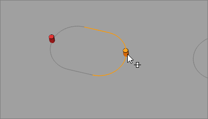
Left-click on a point or edge of a part or FE mesh to place a pin
constraint.
Note: To improve edge selection on FE mesh, adjust the angle in Preferences. -
Select the pin to toggle translation on or off along the edge.
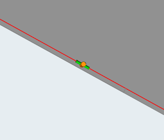
Note: You can not toggle translation if the selected edge is- along the draw direction, or within +/- 2 degrees
- a closed loop
Tip: Apply a pin constraint to multiple edges by holding Ctrl while left-clicking. Once you have selected all necessary
edges, left-click to place the pin constraint.
Add/Edit Blankholder
Use the Blankholder tool to create blankholder constraints.
Blankholder constraints can be defined as the upper and lower holding surfaces that control metal flow around a shape to be formed in a stamping operation. They supply a restraining force on the material during the pressing process.
-
On the Feasibility tab, Constrain
icon, click Blankholder.

Add/Edit Drawbead
Create drawbead constraints with user-defined or preset values.
-
From the Feasibility ribbon,
Setup tools,
Constrain tool group,
click the Drawbead tool.

-
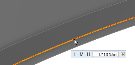
In the microdialog, enter a restraining force for the drawbead, or click a
preset value: L for low, M for
medium, or H for high. Click the reset button
 to restore the drawbead to the default, which is
low.
to restore the drawbead to the default, which is
low.
Keyboard Shortcuts & Mouse Controls
| To do this | Press |
|---|---|
| Select surface or edge groups | Left Mouse Click |
| Select individual surfaces or edges | Ctrl + Left Mouse Click |
| Append/remove feature selection | Ctrl + Left Mouse Click |
| Exit tool | Esc |