Altair HyperMesh 2022 Release Notes
Aeroelasticity
Enhancements
- The position of engine mesh can be aligned as desired using location selection and the Move tool.
- Aeroelasticity set (AELIST) is exported in sorted ascending order of aero element IDs. It is a requirement for solvers.
- Monitor points can be created by selecting a predefined set of sets (AECOMP).
- The Name field is removed from microdialogs for all aeroelasticity tools to be in consistent with other tools. The name can be changed through the Entity Editor. Also, the ID field is removed for Spline, control surfaces, and monitor point tools.
- Tool tips are provided for all aeroelastic entities and their fields through the Entity Editor.
- Removed the Model system option from the CAERO1 Panel Mesh hamburger menu.
- Airbus: Panel meshing using the "Panel mesh" tool is enhanced by direct
selection of LCS. Also, the Move tool has been incorporated to position
panes and their chord sizes before meshing. LCS can also be selected through
a microdialog to define a panel in a local coordinate system. The same Move
tool is used to edit and remesh panels under edit mode.
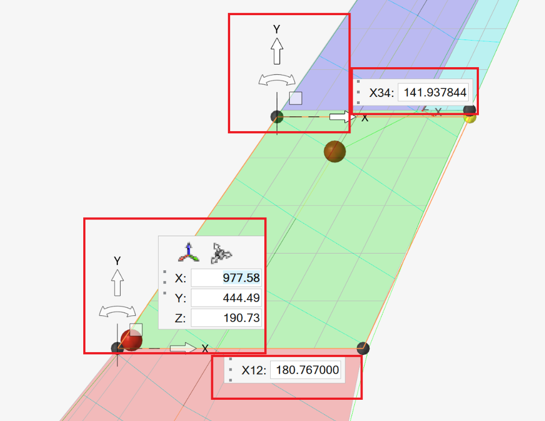
Figure 1. - With the help of location selection and the Move tool, aero bodies can be positioned at the right location before meshing. The same can be repositioned under edit mode by using Move tool as well.
- Location selection and the Move tool are now used to position monitor points.
Resolved Issues
- A performance issue with body/panel meshing on bigger models is resolved.
- An unexpected import warning while importing HMNAME COMP is fixed.
Browsers
Enhancements
- Massive performance improvements
- Around 70% reduction in time for data population in the Model, Include,
Subsystem, and Solver browsers, which improves overall model load
time.
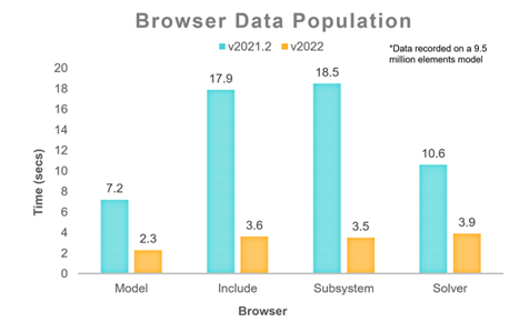
Figure 2. - Embedded EE in Create/Edit dialog
- The embedded Entity Editor is now supported in the Create/Edit dialog for quick editing of referenced entities, which avoids navigation to different pages.
- Parameter context menu
- All the parameter context menu options are now grouped under a
"Parameter" category for ease of use.
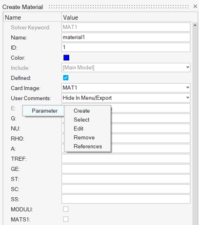
Figure 3. - Restoring of browser on invoke
- All browsers that were open in previous session are now restored at once and tracked by the status bar.
Resolved Issues
- Performance issue while invoking Includes and Subsystem browsers.
- Performance issue with populating Nodes and Elements in browser.
- "Add Metadata" option was missing for certain entities.
- Entity Editor would go blank on editing reference entity ID.
- Crash on selecting temp nodes with regular nodes.
Known Issues
- Entity Editor is not cleared when entity is removed from filtered browser list.
- Collected entities are not updated correctly upon making the respective collectors inactive.
Certification
Enhancements
- Back-end engine improved to support element_nodes and result averaging
-
- Method manager provide options while authoring method template to allow corners and average.
- When created, methods have "Average mode" & "Use corners" options that you can change in HyperMesh for various evaluations.
- Averaging applies to result data types only, not model
attributes.
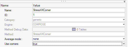
Figure 4. - Result nodal queries (such as displacement) are available and
can be mixed with element data (model or result).
- Nodal results are transferred to element.node value on
each element attached to a node.
No division/average happens.
- This is valid for displacement results but invalid for nodal forces. Instead, use gridpoint force directly with corner "on".
- If a model attribute bounded to an element (area/volume..) is run with nodal results, it is spread to each node and a method is evaluated per node (per element).
- If a result attribute is bounded to an element with a layer (along with nodal result), then the nodal value is spread to each layer and a method evaluated per element.layer.node.
- If element results have corners (and method has corners "true"), then nodal results can be mixed the with element corner values.
- If average mode is used, element results are first averaged to node (with or without corners) then spread to node of element (corner) to run a method per element.(layer).node.
- Whenever element & nodal results are mixed, use the
engine enforce system for extraction in Global to keep
data consistent.
- Note that "Analysis system" is usually different for elements and nodes. The back-end engine was improved to support element_nodes and result averaging.
- A warning message is posted in the Run report.
For more information, see the log file.
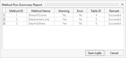
Figure 5.
- Nodal results are transferred to element.node value on
each element attached to a node.
- Run method on elements
-
- Methods can be evaluated on FE elements directly without creation of designpoint and designpointset.
- This is valid if method inputs does not require structural property and if there is no sorting defined that implies aggregation across elements.
- A new option is added to select the system for component
extraction.
- In the event of averaging or nodal result being used by a method, the system will switch to the global system.
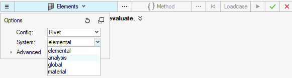
Figure 6.
- Structural Element detection
-
- New Split option in Panel & Generic Structural Element
detection
- split by element's property
- split by element's component
- For panels, the split is performed after topology detection. If
1D are used with shell, then panels are first detected, then
split applies to detected panels.
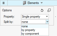
Figure 7.
- New Split option in Panel & Generic Structural Element
detection
- Structural Property made optional
-
- Run is no longer prevented for designpoints without structural property.
- First ply failure method can now run on panels without
structural property.
- The engine will then collect elemental properties directly to evaluate a method per element.
- If a structural property is applied, then the assigned property takes precedence over the element's property for all elements in the same panel.
Known Issues
In method contour, it is possible to select "nodeids" result on nodes (or corners).
This will result in a nodal contour with unique values on nodes.
- If results where saved as corner data (node of element), then the displayed contour is the aggregated value.
- Aggregation follows the general Sort key (min|max|absmin|absmax ) in contour
UI already used whenever an aggregation happens (accross loadcases or
layers).
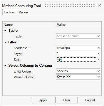
Figure 8.
Resolved Issues
- Fixed issue when multiple freebodysections referring to the same elements
where used.
- Results used to be saved against elementID (so values were lost for some freebodysections).
- Result structurse now account for entityID.elementID. where entityID
is freebodysection ID.
For non-entity based methods (bounded to element), the table shows an entityID the same as the designpoint ID.
Composites
New Features
- Filament Winding Workflow
-
- Through ply types, filament winding simulation data from APA software can be directly imported. Zone based properties per element are no longer used or required.
- Filament winding data is displayed and can be reviewed for each winding angle.
- Models can be directly solved in OptiStruct and post-processed using .h3d data.
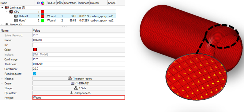
Figure 9. - Composite Stress Toolbox
-
- Line plots for selected results of material, ply, and laminate
engineering constants analyses.
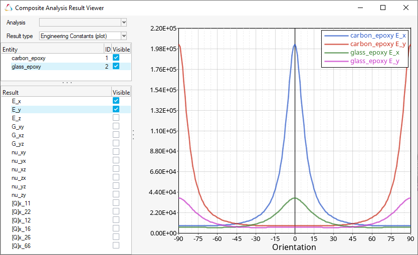
Figure 10. - Through-thickness plots for selected load response/failure
results.
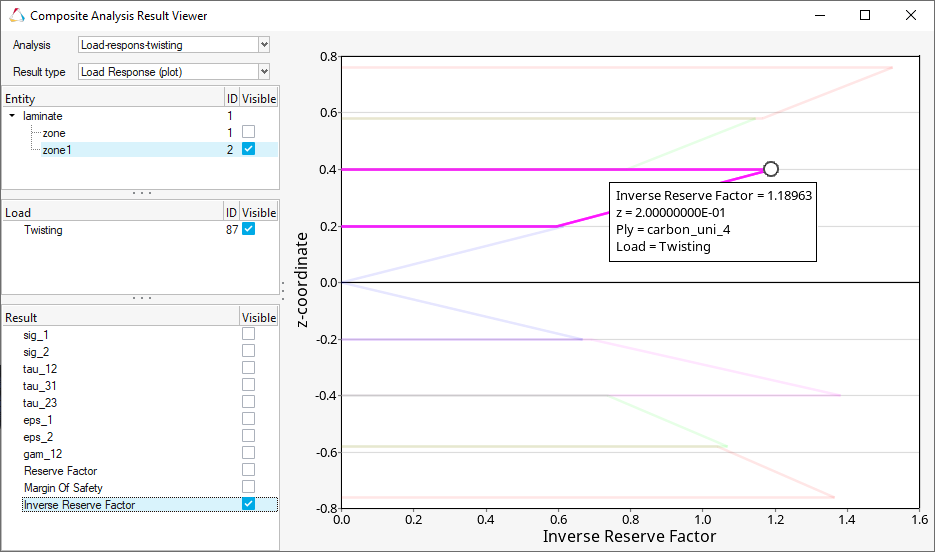
Figure 11.
- Line plots for selected results of material, ply, and laminate
engineering constants analyses.
Enhancements
- General
-
- "Automatically update sets to mesh changes" feature now available for sets generated from ply realization.
- Composite Stress Toolbox
-
- Wrinkling failure in First Ply Failure method is now supported for Abaqus laminate load response and strength analyses.
- All results can be accessed from one, new consolidated viewer.
This includes:
- Seamless switching between various analyses and result representations (tables and plots)
- Style enhancements for improved readability of numeric results
- Numerous smaller enhancements:
- Ply type has been added to engineering constants results
- Min/max highlighting has been added to the first-ply-failure result table in laminate load response analysis
- Default position and size cover Model View area
Known Issues
- General
-
- Laminate and ply edit performance for large models. A workaround is to stack a ply with no shape temporarily in the laminate.
- Detailed thickness review with ply layers of Wound ply type does not take drape data into account correctly. This fix will be in 2022.1.
- Import performance of filament wound models with more than ~150k elements
Resolved Issues
- General
-
- Performance of mass calc for models with many laminates
- Laminate realization segmentation error when unsupported element types passed
- Spreadsheet import of multiple sets only tool first set ID in list
- Composite Stress Toolbox
-
- Running laminate engineering constants analysis with n sub-laminates of the same interface laminate would lead to n-times the zones of the interface laminate to be shown in the results. Now they are only shown once.
- Filtering would malfunction for laminate reserve factor for mixed failure criteria (plies and wrinkling) in certain circumstances.
- Load response analysis for laminates with plies of type “Shell to Solid Layer Divider” would crash.
Connectors
New Features
- Post Script Removal
-
- Any realization without a post script will now automatically create properties and materials dependant on the element in the body of the realization.
- The property option "None" has been removed; it is now
simplified to specify a Property/Material or leave it
undefined.
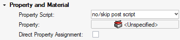
Figure 12. - The following realizations have had their post scripts set to
No/Skip when created through Controls as they are no longer required:
- Spot Types
-
- acm (detached-(T1+T2)/2)
- acm (equivalenced-(T1+T2)/2)
- acm (general)
- acm (shell gap)
- Bolt Types
-
- bolt (2 cylinder rigid)
- bolt (b31)
- bolt (cylinder bar)
- bolt (cylinder rigid)
- bolt (step hole)
- bolt (threaded step hole)
- BUSH cylinder
- hinge
- hinge (b31)
- Line Types
-
- adhesive-hemmings
- adhesives
- HC mig weld
- hexa (adhesive)
- hexa (RBE2-RBE3)
- rigid (crbody) HC laser
- Connector Imprint Generalisation
-
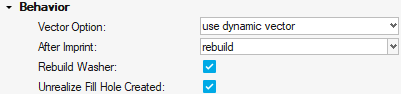
Figure 13.- Rebuild is now available post imprinting for better a quality mesh.
- Rebuild is now optionally available for the Washer if it interacts with feature edges to improve mesh quality.
- If a Bolt connector creates a hole during realization, it can now be filled on unrealization.
- Metadata Mapping from Parts
- Allow the metadata on a given part to be mapped to the connector as
links and metadata.
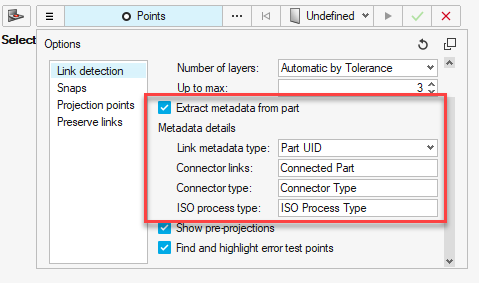
Figure 14.
Enhancements
- Realizations
-
- Bolt(Metal Clip) has undergone a significant upgrade:
- The body elements can be changed within the control/connector.
- Any change in the vector is now remembered locally on the connector with the use of the "Overwrite Attribute" flag.
- Materials and Properties can now be selected and filtered from a default location.
- The tower and hole elements are placed in a contact set in LS-DYNA and PAM-CRASH.
- Hexa Imprint (adhesive contact) + Penta Imrpint (adhesive
contact)
- Contact type changed to Shell Edge to Surface in LS-DYNA.
- Part Set is now default for the Secondary set in LS-DYNA.
- Bolt(Metal Clip) has undergone a significant upgrade:
- xMCF
-
- A new mechanism to add HyperMesh information into the xMCF format has been added under the export option "App Data Block". This will export the Connector details including the Connector Controls.
- A new mechanism to add the Realization information into the xMCF format has been added under the export option "FEM Data Block". This will export the element types and references into the FEM Data Block. It will also add the PID of the realization.
- Property Links historically have been converted into Component links when exporting xMCF. This has been reverted and will now directly export the links as Property References.
- Workflows
-
- "Create New" in the Connector tools now say "Create New/Edit" when controls exist.
- "Create New" now creates a control if there are no controls.
- Double clicking connectors in the Model Browser now filters the Connector Browser.
- Instance links now shown on Attachments in the Connector Browser.
- Absorption
- Absorbing connectors allows the assignment of the property to the
connector during the absorption process.
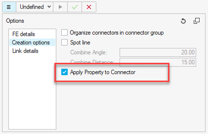
Figure 15.
Resolved Issues
- xMCF Clip are now classified as a Bolt, in line with the realization types.
- For a spot line where each spot can fail independently of the rest of the line, a "Partial Realisation Option" has been added where X% of the Connector needs to realized for the Connector to be marked realized.
- Systems created in Spot Lines will now have the Z axis follow the Spot Line Direction.
- Merge Lines in the Create tools now no longer require all the lines to be selected at once.
- Attachment REM issues fixed for Attachments that are referenced.
- Loading Parts with Connector Groups as instances was causing a crash. This has now been fixed.
- Attachment performance has been improved with unrealizing/realizing and creation.
- Importing a Binary or XML of Connectors or Attachments where the Part ID no longer exists was causing the UID to be lost. This has now been fixed.
- Connector Lines/Spot Line XMLs are now independent of the pitch size. The accuracy of the shape of the line should not change when exporting/importing.
- Connectors when realizing to a Solid mesh were selecting internal faces. They will now only realize to external faces of the Solid mesh.
- The option to realize the internal/external face of a Solid mesh is now available. The option is on the Connectors/Controls as "Solid Outer Face".
- When saving Attachments into a Connector Group, the Controls were not saved with the Connector Group. This has now been corrected and the controls are saved.
- Absorbing Connectors with links that are instances of the same part will now append each instance of the part to the Connector.
- Connector Lines/Spot Lines now have different End Offset options. The
graphics have been updated to indicate directionality of the Connector.

Figure 16.
Fields
Enhancements
Supports direct results mapping for:
- H3D
General
New Features
- HyperWorks Startup dialog
- In the Windows Start menu, individual client shortcuts are replaced by a single HyperWorks shortcut that prompts you to pick the client, profile, directory, or recent models and sessions.
- Move tool orientation improvements
-
- When repositioning the Move tool manually (via double-click or holding Shift), its designated position will now be honored even when modifying the guide bar selector. It will only reset back to its automatic position (selection centroid) when resetting the selection, or clicking the Align button in the Move Tool microdialog.
 - Click once to reset the move tool
orientation to match the global coordinate system (or local
system, if assigned). Click twice to also reset its position to
the selection centroid (or local system origin, if
assigned).
- Click once to reset the move tool
orientation to match the global coordinate system (or local
system, if assigned). Click twice to also reset its position to
the selection centroid (or local system origin, if
assigned). - Select and assign a local
rectangular coordinate system to the Move tool. After a new
system is assigned, the Move tool will automatically reposition
to its origin.
- Select and assign a local
rectangular coordinate system to the Move tool. After a new
system is assigned, the Move tool will automatically reposition
to its origin.
- Custom ribbon dialogs
- A custom ribbon can now be converted into a floating dialog. To do this, right-click on the ribbon name and select Float. Closing the dialog will bring its content back to the ribbon area.
- New snap styles
- Added Element Mid Edge and Features: Hole Center.
Enhancements
- The order of the ribbons has been adjusted to better reflect a typical modeling workflow.
- Application and graphics performance presets have been added to the HyperWorks Performance preferences.
- A new export option is added for HyperMesh component comments that will preserve the integrity of the solver deck with our previous releases. This option is added for Nastran and OptiStruct solver profiles.
- Selection undo/redo support for entity selectors of type Locations, Faces, and Edges.
- Added Ctrl+Shift shortcut to trigger View Simplification mode while being held.
Resolved Issues
- Application crashes when using the scrollbar in a browser while running remotely on Linux.
- An occasional crash seen when switching between contexts in a Sketcher workflow.
- A crash seen on shutdown when Entity View browser is open.
- Transformation tool is slow while transforming loads.
- Organizing Tags associated to the nodes.
- Select By ID: Issue pasting ID lists containing special carriage return (CR) characters is now resolved.
- Model becoming accidentally hidden when selecting nodes after disabling the Empty Space snap.
- In a context menu with a pull-right, the new menu does not disappear immediately when you move your mouse down.
- Move tool now remembers its position after using a pushable tool such as Show/Hide or Measure.
Known Issues
- The section name "AddOn" is no longer supported in the extension.xml file. Only "Extension" is supported from version 2022 onwards.
Geometry
New Features
- FE Geometry
- FE geometry is topology on top of mesh, meaning CAD and mesh exist as a single entity. The purpose of FE geometry is to add vertices, edges, surfaces, & solids on FE models which have no CAD geometry. Tools and workflows operate similarly on CAD and FE. With FE geometry, mesh selections are made easier as they are topology-based selections. FE geometry can be used for 1D and 2D elements. It is recommended to use FE geometry where there is no CAD associated to mesh.
- Unsplit
- New HyperWorks Unsplit workflow added to remove split lines so split surfaces return to their original unsplit state.
Enhancements
- Geometry can be created as CAD geometry or FE Geometry by setting create mode under Geometry preferences.
- Most of the geometry creating and editing tools have been instrumented to support FE geometry. This allows use of CAD editing tools on elements.
- Autocleanup functionality is supported fully under Defeature – Batch tool.
- Sketch - Intersect tool now supports intersection of 2D and 3D elements while creating reference plane.
- Enhancements made to surface patch tool include:
- Improved loop detection
- Improved stitching of patched surfaces
- Improvements on patch algorithm to avoid patch failures
- Enhanced defeaturing of fillets
- Updated workflow help showing new options supported by geometry tools.
Resolved Issues
- Fixed robustness issues related to Sketch, Drag, Imprint, and Cross Extend tools.
Known Issues
- If a solver deck is imported with the Create FE geometry option "on", or a portion of the model is converted to FE geometry, HyperMesh post functionalities are lost. You need to delete the FE geometry present in the model before proceeding to HyperMesh post-processing.
- Assign plot contour is not supported for FE geom elements in the Check Elements (F10) 1D & 2D panel.
Matrix Browser
Enhancements
- Multiple result queries can be executed while in the Matrix Results Query dialog without the need to reopen the dialog.
- Macro recording supports HyperMesh result queries.
- GUI enhancement allows adjusting the frame split position between the table and the query columns.
- Added support for the following element data names: refx, refy, refz and plylist.
- You can now choose to populate the entity query ID column in an increasing or decreasing order. By default, the entity IDs are returned in the order they have been generated in the HyperMesh database.
- Matrix settings have been moved to the Post section of the general Preferences dialog.
Resolved Issues
- Certain integer type data names were previously reported as floating values. They are now correctly returned as integers.
Meshing
New Features
- Associate Tool
- New context-based workflow added for nodes and elements association in the Elements ribbon, Edit Elements tool. This tool helps you detect and graphically review associated and non-associated nodes, perform local association, disassociation, and correction of wrong association.
- Mesh Controls
- Mapped Mesh and Edge Biasing local control newly added under Surface
mesh. Mapped control along with Edge biasing helps you get structured
mesh on four sided faces.
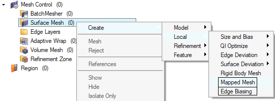
Figure 17.
Enhancements
- Midmesh
- Midmesh default extraction output will be FE geometry only. Geometry tools and contexts can be used to edit midmesh output for quick topology editing.
- Legend
-
- Display of maximum node or elements id is supported.
- Text color for no results contour is shown in dark color.
- Batchmesher
-
- Element quality failures have been reduced by allowing aggressive node movements for failed elements. This is provided by introducing “Aggressive quality correction” parameter in the parameter file.
- Better body fillet identification to maintain continuity and mesh flow.
- Mesh Controls
-
- Under Global feature mesh control, “Identify features and mesh” option added. This detects features like cylindrical, fillet faces and meshes them with mapped ISO mesh. Similarly, global washer creation option added.
- Face mesh control updated with Layers option. This helps with creating a specific number of layers on selected faces, either constant size or stretched.
- Added option to controlthe number of mesh affected layers for CAD/FE geometry topology editing, such as split and unsplit. This option can be set from the meshing preferences.
- Added Quad only and R-Trias element type option for solid map.
- Thickness mapping tool ignores surfaces associated to target mesh.
- Added legend with show, hide, and isolate option for Face Edit in Panel meshing.
Resolved Issues
- 3D meshing: BL chop off layers related bug has been addressed.
- Addressed RBE3 elements support with Replicate tool.
- Fixed crash on selection of elements “by surface” for model with mass elements.
- Fixed crash when using Auto Quad in Refine tool.
- Fixed rigid elements getting detached on component scaling.
Model Build
Enhancements
- General performance enhancements for Part Browser workflows.
Resolved Issues
- Hierarchy issues are fixed.
Model Verification
Enhancements
- All the MVD GUIs are redesigned to suit the new HyperWorks interface look and feel.
- Tool tips and images are included for all of the GUI parameters.
- Progress/status messages from each GUI is shown at the left bottom of HW session.
- Comparison
-
- UID attribute is supported in Comparison and BOM Comparison.
- With new parameter, Comparison will show 100% match if maximum gap between CAD and FE is less than 0.03mm.
- cadtofeapproach is implemented for CAD-CAD and CAD-FE parameter in the config file.
- "skip assembly" parameter is extended to Q comparison.
- Intersection and Offset
-
- New parameter added to filter duplicate intersection reports on symmetry parts.
- Comparison function can be called within Offset function to compare the shape after surface offset.
- Spot Weld
-
- Spot comparison outputs matched and unmatched connectors file to the report folder.
- Spot comparison base and variant connectors will have separate report color that can be tuned from configuration.
- Spot weld, missing weld check is improved to avoid detecting false reports near fillets, steps and holes.
- Spotweld missing weld report name will contain Connected link IDs.
Resolved Issues
- Q-compare legend guide bar was not working for hiding elements.
- For the CAD Step format, .step extensions were not working while importing step files.
- Partial match% value in BOM compare was not taken from compare GUI.
- Unmatched elements were not shown for Q-compare review result when "comparison_result.hm" was used.
- Multivariants comparison check was not working.
- Q compare review result did not take component color.
- Unable to run spot-compare if comparison type was spot file and FE/CAD.
- Intersection Check did not complete for a few complex models.
- Report was missed for Boltnutsize-mismatch with diameter bolt 7.2mm & nut 8mm.
Morphing
Resolved Issues
- Mouse wheel zoom stopped working some times when exiting a morphing tool immediately after a morphing operation.
- Free Morphing: Issue with hidden connected nodes being considered for auto-selection of morph area or anchors has been resolved.
- Fixed an issue with the Move manipulator flipping orientation when performing a right-click in the graphics area.
- Application would some times crash when entering and exiting some morph tools in quick succession.
Post
Enhancements
- Official support of ANSYS and Abaqus solver profiles for plotting workflows (beta flag has been removed)
Resolved Issues
- Major fixes for results contour on mid-side nodes for 2nd order elements
- Fix of 1D vector orientation
Safety Tools
New Features
- Dummy Testdata Positioning
- This new feature introduced in the Dummy Positioner tool enables the automatic positioning of an FE Dummy model based on test-lab coordinates measurements data. This tool leads to an important time reduction in the process of positioning dummies in the vehicle. Once the positioning is completed, you have direct visual feedback with the target points entity graphics on the positioning accuracy of the dummy.
Enhancements
- Mechanism Constraints
- The existing Constraints entity used in the Mechanism tool is renamed to Mechanismconstraints entity. This allows for using the Constraints entity as a solver entity.
Skeleton Modeling
New Features
- Introduction of Skeleton Modeling
- The skeleton modeling functionality provides a mechanism to create a reduced ordered model to facilitate optimization at the concept phase.
- A skeleton model can be derived from several different sources. The most
common sources are donor FE and CAD geometry. All the sources shown in
the image are supported, including direct interpretation from topology
results.
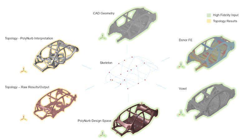
Figure 18. - The skeleton model build process is dissected into three key stages –
Joints, Members, and Panels. The image below shows the source input, the
skeleton model build phase, and then the reduced order skeleton
model.
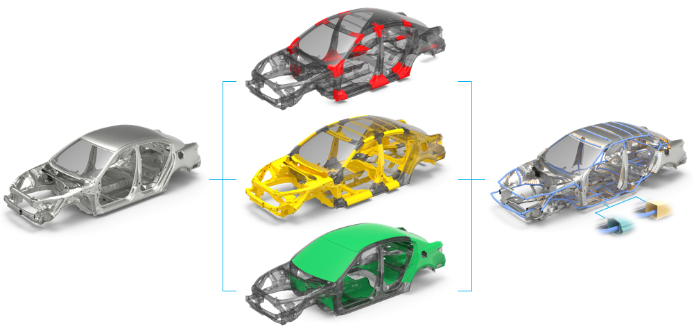
Figure 19.
Solver Attribute Mapping
Solver Conversion
Enhancements
- Abaqus to OptiStruct conversion
-
- CPS4 and CPS3 elements converted to CQUAD4 and CTRIA3
- FRICTION converted to PCONT, FRICSEL
- GASKET material converted to MGASK, TABLEG
- ROTATION joint converted to ROTATION joint
- CARTESIAN, ROTATION converted to CARTROTA joint
- Nonstructural Mass converted to NSML1
- HEADER in the include file is moved to master include on conversion
- TIMEPOINTS converted to NLOUT, TIME, SET,<NUM>,time, list
- Tags are retained on conversion
- Radioss to OptiStruct conversion
-
- /MAT/PLAS_TAB material converted to MATS1,TABLEMD
- TYPE2 contact converted to TIE contact
- Abaqus to Radioss conversion
-
- SUPERELASTIC material converted to LAW71
- General Contact converted to TYPE24 OR TYPE25
- Pamcrash to Radioss conversion
-
- MPART(Type=Solid) converted to /PROP/SOLID
- MPART(Type=Shell) converted /PROP/SHELL
- CNTCT33 converted to TYPE7
- GROUP(components) SURF/PART/EXT
- Basic Entity Mapping
- Sets and contacts card images are mapped on switching profiles across
the following interfaces:
Abaqus, OptiStruct, Nastran, NX Nastran, Ansys, Dyna, Pamcrash, Radioss, Permas, Samcef, and ADVC
CAD and Solver Interfaces
Abaqus Interface
New Features
- New entity for surface-based couplings
- Element-based surface couplings from group and Node-based surface couplings from panel are migrated to new Constraint entity.
- Component migration
- Removed solver dependency on components. This includes element set removed from *ELEMENT and created as new *ELSET entity. Indirect assignment of property is not supported by including HW generated element set for property.
Enhancements
- New keywords
- *COUPLED THERMAL-ELECTRICAL
*MASS ADJUST
*PLASTIC M1
*PLASTIC M2
*PLASTIC TORQUE
*PLASTIC AXIAL
*FRAME SECTION
- New Elements
- FRAME2D
FRAME3D
SHEAR4
- Updated Keywords
-
- DLOAD card updated with support of TRSHR (Traction shear).
- Compression factor added to *ELASTIC.
- Actuator definition added to *AMPLITUDE.
- Temperature field added to *UNIAXIAL.
- *SURFACE now carries SPOS/SNEG for shell element faces.
Resolved Issues
- Names exceeding 32 characters are allowed for parameter entity.
- Color column added for Contact Browser.
- Order of writing node set by element set issue is resolved.
- An issue with property lost on *EULERIAN SECTION is resolved.
- An issue with set names changing on multi-import is fixed.
- Name pool caused database corruption with duplicate names for some cards on sets. This issue is fixed.
ADVC Interface
Enhancements
- All float values are now exported in exponential format. Positive values have 12 digits (6 digits after decimals) and negative and zero values have 11 digits (5 digits after decimals).
- Pretension directional vector component can be selected through graphics manipulator in addition to manual inputs.
- load_id check box is added for $Load and $Pressure. You can turn it ON as per Random Response Analysis Set Up.
Resolved Issues
- Fixed a bug in custom import options where Loads and LoadCols were not working.
- Fixed a bug where HyperMesh crashes if you import a file name that contains Japanese 2byte characters.
- Fixed a bug where PhysicalQuantity and TimeStepControls were missing in the browser configuration.
- Fixed a bug where the Behavior entity was not listed for the Includes View.
ANSYS Interface
Enhancements
- Removed HM_COMP card image on the component.
- New section entity is supported.
- Removed contact element support on components.
- Both section and Real (for supported types) can be mapped to properties.
- On import, create unique Properties with Material and Sensor assignment.
- Import options (By Material, Property, and One Component) are supported.
- Direct assignment of elements to properties is supported.
CAD Interface
Enhancements
- Updated version support
-
- NX 1969 (CT reader)
- Creo 8.0
- Support for reading Neutral files made with Creo 8 or earlier
- Parasolid 33.1.154
Resolved Issues
- Fixed instance attribute name to match with Catia.
- Fixed BOM import issue with step AP242 file.
- Improved Catia import performance issues with models having large no of fillets.
- Fixed crash on import of OCX file exported from CADMATIC.
- Fixed Catia parameter import issue due to space in parameter name .
EXODUS Interface
New Features
- Auto-contact is now available for the EXODUS user profile.
- Mesh Group entity supported.
Enhancements
- All function/curve types can now be defined in EXODUS profile.
Known Issues
- Mesh groups can be defined on blocks, sidesets, and node sets but not on another mesh group.
- Direct property assignment
Resolved Issues
- Upon changing element order, update the distribution factor for sidesets.
LS-DYNA Interface
New Features
- New Integration Rules entity
- LS-DYNA keywords *INTEGRATION_SHELL and *INTEGRATION_BEAM, previously supported in Property entity, are now mapped to their own entity.
- New Perturbation entity
- LS-DYNA keywords *DEFINE_STOCHASTIC_VARATION and *DEFINE_STOCHASTIC_VARATION_PROPERTIES, previously supported in Property entity, are now mapped to their own entity.
- New Frequency entity
- LS-DYNA keywords *FEQUENCY_DOMAIN_(OPTIONS) are now supported and mapped to the new Frequency entity.
Enhancements
- New Keywords
-
- *CONSTRAINED_LINEAR_GLOBAL
- *CONSTRAINED_LINEAR_LOCAL
- *DEFINE_FUNCTION_TABULATED
- *EOS_JWLB
- *EOS_MIE_GRUNEISEN
- *EOS_GASKET
- *EOS_MURNAGHAN
- *EOS_PHASE_CHANGE
- *MAT_MODIFIED_JOHNSON_COOK (*MAT_107)
- *MAT_DAMAGE_3 (*MAT_153)
- *MAT_MUSCLE (*MAT_156)
- *MAT_MOHR_COULOMB (*MAT_173)
- *MAT_NON_QUADRATIC_FAILURE (*MAT_258)
- *PART_AVERAGE
- *SENSOR_DEFINE_FUNCTION
- *SET_NODE_LIST_SMOOTH
- Updated Keywords
-
- Update in *CONSTRAINED_INTERPOLATION to support independent nodes with a *SET_NODE when ITYP=1
- LS-DYNA R11.1: New ELFORM value in *SECTION_SOLID
- LS-DYNA R12.0: Updates in *EOS_GRUNEISEN and *EOS_TABULATED_COMPACTION
- Solver Mass entity management
- A new option in the Appearance Preferences allows you to display the graphics on nodal masses defined inside the *ELEMENT_MASS Solvermass entity.
Resolved Issues
- Export Solver Deck feature, when selecting a material linked to multiple MAT_ADD cards: all linked MAT_ADD keywords are now exported with the selected material.
- Removed Title checkbox in *DEFINE_FUNCTION keyword Entity Editor.
Nastran Interface
New Features
- LoadStep inputs entity
- Bulk cards like RLOAD1/2, TLOAD1/2, DLOAD, ACSRCE, and RGYRO are migrated to loadstep inputs entity.
Enhancements
- Export solver card option from Model Browser right-click context extended to Nastran interface.
- New solver option in Export Browser to export solver input with HMMOVE and HMDPRP comments.
Resolved Issues
- CORD3R to CORD1R conversion on export using Nastran template
- Incorrect export of coordinate systems with referenced system
- Incorrect face assignment while creating PLOAD4 on pyramid elements
OptiStruct Interface
New Features
- Electrical Analysis
- New bulk cards to setup electric analysis:
- Materials
- Loads
- Subcase selection and analysis types
- LoadStep inputs entity
- Bulk cards like RLOAD1/2, TLOAD1/2, DLOAD, ACSRCE, UNBALNC, and RGYRO are migrated to loadstep inputs entity.
Enhancements
- New bulk card and subcase selection CNTITF to define parameters for contact interference.
- New solver option in Export Browser to export MPC and CORD2/CORD4 cards in large field format.
- Export solver card option from Model Browser right-click context extended to OptiStruct interface.
- New solver option in Export Browser to export solver input with HMMOVE and HMDPRP comments.
- MAT9OR and MATMDS materials are allowed to assign to PLY, PCOMP, PCOMPG, PSHELL cards.
Resolved Issues
- CORD3R to CORD1R conversion on export using Nastran template
- RBE2 model checks to be consistent with OptiStruct solver checks
- Incorrect export of coordinate systems with referenced system
- Unable to reference a transient subcase in DESOBJ
- Incorrect face assignment while creating PLOAD4 on pyramid elements
PAM-CRASH Interface
New Features
- PAM-CRASH Solver Version 2021
- The latest new Pamcrash2G2021 solver profile is now supported.
- Export Solver Deck
- New context menu option Export Solver Deck available for all solver entities in the browsers (Model, Entity View, Solver). Export selected entities and all their references directly to a solver deck.
- New Friction Entity
- Keywords FRICT and FRITAB are now supported as a dedicated Friction entity type and moved out from the Property entity type. Also, the assignment of the friction entity is enabled in the PAM-CRASH Contact and Slipring keywords.
- New Keywords
- FRITAB/
Enhancements
- Friction Entity Selection
- The assignment of the friction entity is enabled in the PAM-CRASH contact and slipring keywords; this is after FRICT and FRITAB keywords mapped to new Friction entity type.
- Removed Solver Profiles
- Legacy PAM-CRASH solver profiles Pamcrash2G2012, Pamcrash2G2013, and Pamcrash2G2014 are removed. Templates are available only in the installation; however, they are no longer maintained.
- Updated Keywords
- FRICT /
CNTAC
SLIPR /
Radioss Interface
New Features
- Radioss V2022 Profile
- The new Radioss 2022 profile is added and supports the latest solver version.
- Unit Conversion
- The new unit conversion tool in the Model ribbon provides an efficient way to convert a model from its original unit system to a new unit system.
Enhancements
- New Keywords
- The following Radioss keywords have been added:
- Updated Keywords
- The following Radioss keywords have been updated accordning to the latest solver manual: