HWCFD-T: 2000 Meshing
In this tutorial, you will cover the various meshing tools and options that are available in HyperWorks CFD. The five major mesh controls covered are:
- Surface
- Gap
- Boundary Layer
- Volume Mesh
- Zones
Before you begin, click here to download the tutorial models. Extract mixingTank_base.hm from the zip file.
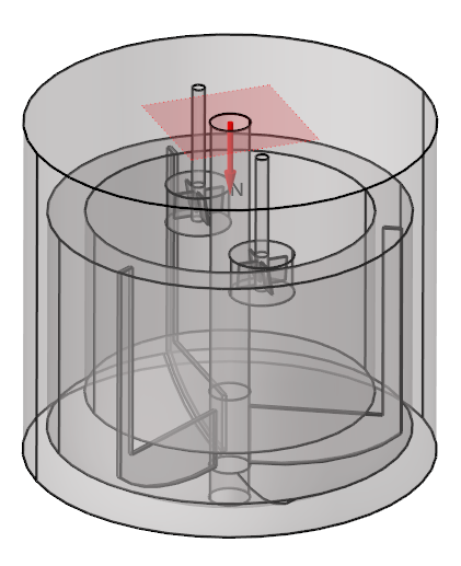
Figure 1.
Set Up Surface Mesh Controls
-
Click the Surface tool.

Figure 2. -
On the guide bar, click
 to execute the command and remain in the
tool.
to execute the command and remain in the
tool.
-
On the guide bar, click
to execute the command and remain in the
tool.
-
On the guide bar, click
 to execute
the command and exit the tool.
to execute
the command and exit the tool.
Assign a Gap Control for the Whole Geometry
-
Click the Gap tool.

Figure 3. -
On the guide bar, click
to execute
the command and exit the tool.
Set Up Boundary Layers on the Rotating Impellers
-
Click the Boundary Layer
tool.

Figure 4. -
On the guide bar, click
to execute the command and remain in the
tool.
-
On the guide bar, click
to execute the command and remain in the
tool.
-
On the guide bar, click
to execute the command and remain in the
tool.
-
On the guide bar, click
to execute
the command and exit the tool.
Assign Volume Mesh Controls to the Small Impellers
-
Click the Volume Mesh
tool.

Figure 5. -
On the guide bar, click
to execute
the command and exit the tool.
Create a Refinement Zone for the Mixing Domain
-
From the Zones tool group, click the
Cylinder tool.

Figure 6. -
Snap the cylindrical zone to the center of the shaft as shown in Figure 7. Drag your
mouse and click anywhere on the screen to define a temporary size for the
cylinder. In the radius microdialog, enter a value of
0.54 and press Enter.
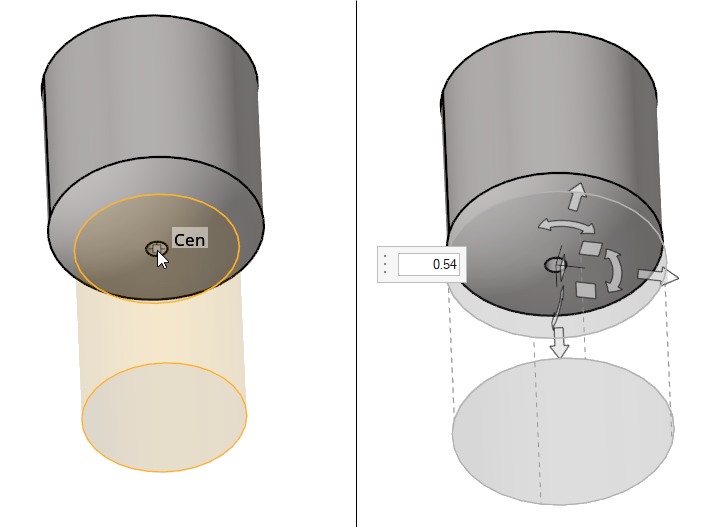
Figure 7. -
Enter a value of -0.86 then press Enter to move the zone along the negative Y
direction.
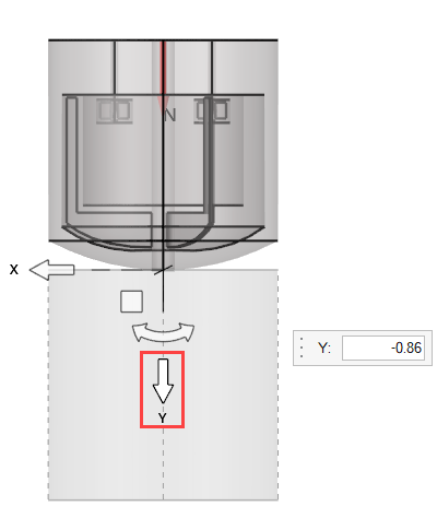
Figure 8. -
Enter a value of 0.0025 for the mesh size.
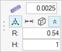
Figure 9.
Run a Surface/Volume Batch Mesh
-
Click the Volume tool.

Figure 10. -
Click Mesh to execute the batch mesh process.
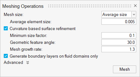
Figure 11.