Define Weld Evaluation Point Properties
Use the Points tool to define the properties of the weld lines considered in the evaluation.
Before defining point
properties, first apply a regulation using the Specifications
tool.
-
Click the Points tool.

Figure 1.The Evaluation Points dialog opens. -
Edit the general parameters and the location parameters for the weld by
selecting options from the drop-down menus or entering values in the text
boxes.
Note: The properties available in each table are updated according to the specification selected.Each point is defined at the evaluation distance specified in the General table and is measured from the weld segment centroid.
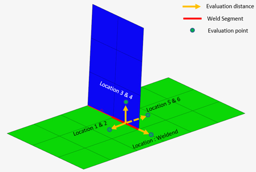
Figure 2. - Optional:
Click
 to import a Weld Property file
(.xml) containing the data of all the classification
parameters with respect to each weld line.
to import a Weld Property file
(.xml) containing the data of all the classification
parameters with respect to each weld line.
- Optional:
Click
 to save the data of all the classification
parameters with respect to each weld line.
to save the data of all the classification
parameters with respect to each weld line.
Exported files can be used in a later run when defining a weld specification.
An additional evaluation point will be added for a weld end. Its evaluation distance will be measured from the free end of the weld segment. The weldend will be listed in the location table of points context and will be evaluated when the preference option Enable Weld End Evaluation is activated.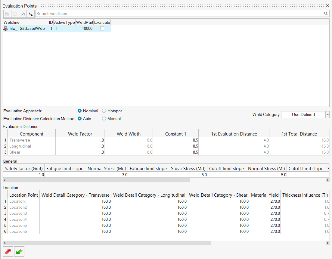
Figure 3.
Materials for Stress Life Welded Evaluation
Assign material weld location for stress life evaluation.
-
Click the Material tool.

Figure 4.The Evaluation Points dialog opens. -
Click the Points tool.
Figure 5.The Evaluation Points dialog opens. -
Select a weld line.
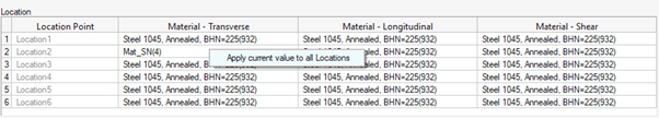
Figure 6.