HV-6020: Using Video Overlay
In this tutorial you will learn how to use video overlay.
- Import and edit an image
- Overlay the image on top of an animation file and play the animation
- Import a video as a 2D image
- Overlay the video with an animation file and play the animation
- Align a video using multiple point alignment or camera properties
- Import a video as a 3D image
- Rotate and animate the video and animation file together
- Click the Image Plane tool button on the Annotations toolbar
 .
.OR
- From the Results Browser right click and select .
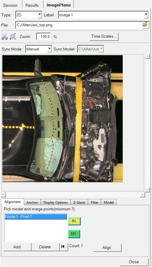
Figure 1.
The Image Plane tool allows you to import images and video files to the HyperView animation window. These images and videos can be edited and graphically placed in the animation window. They can also be imported as 2D images or 3D images which can be rotated in the graphics window just like a results file. The videos can be animated and synchronized to an animation file. See the Image Planes
topic for additional information.Import and Edit an Image, then Animate the Model
-
Within the Results Browser, expand the Section Cuts folder
and click on the
 icon next to Section 2.
The display of the section cut for Section 2 is turned off in the graphics area.
icon next to Section 2.
The display of the section cut for Section 2 is turned off in the graphics area. -
Click the Image Plane panel button on the Annotations toolbar.
-
Click on the Open File icon
 next to File and select the file altair.png.
The file is imported into the animation window.Note: The size of the image in the animation window.
next to File and select the file altair.png.
The file is imported into the animation window.Note: The size of the image in the animation window. -
To resize the image, click on any of the corners of the graphical manipulator
and drag to the new desired location. Resize the image as shown below:
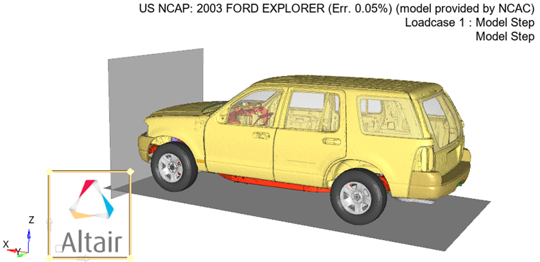 Figure 2.
 -
To move the image, use the graphical manipulator in the lower left corner of
the image. Click on the horizontal axis to move the image horizontally, and
click on the vertical axis to move vertically. Center the image in the graphics
window as shown below:
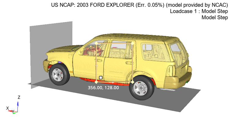 Figure 3.
 You can also place the image at the center of the animation window by clicking on the Anchor tab in the Image Plane panel and selecting the Center icon
 .
. -
Notice how the image cannot be seen because it lies under the animation. To
bring the image to the front, click on the Z-Stack tab in
the Image Plane panel and with the image label (Altair) highlighted, click the
up arrow
 .
.
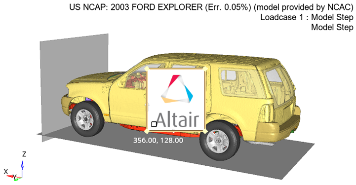 Figure 4.
 -
Click on the Filter tab. Using this tab, the color white
will be removed from the image so that is has a transparent background.
-
Click on the Color option and pick the gray
color (just below white) from the color palette.
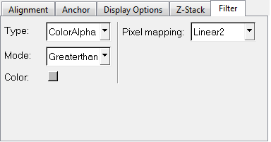 Figure 5.
 These settings remove the color white from the image.
-
Click on the Color option and pick the gray
color (just below white) from the color palette.
-
Animate the model.
Note: The model animates with the image placed on top of the model.
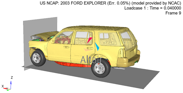 Figure 6.
Import a Video and Animate with Model
-
Select the XZ Right Plane View
 to align the h3d model and the avi file in the same
plane.
to align the h3d model and the avi file in the same
plane.
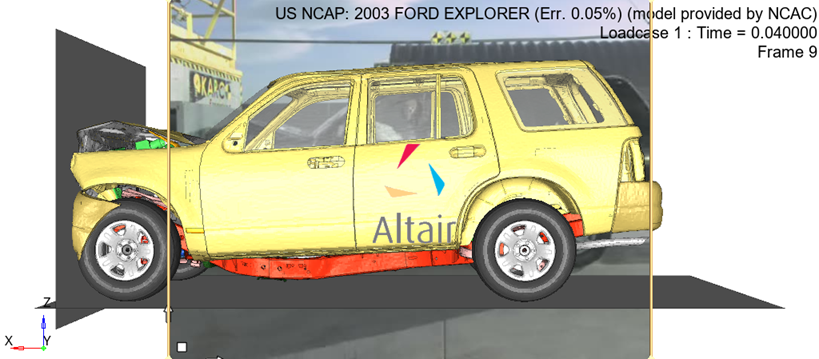 Figure 7.
 -
Resize and move the image in the same manner as the
altair.png file.
-
Resize and move the image to match the size and location of the
model.
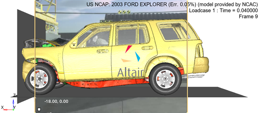 Figure 8.
-
Resize and move the image to match the size and location of the
model.
Align a Video Using Multiple Point Alignment or by Entering Camera Properties
-
From the Image Plane panel, click on the Alignment
sub-tab. This sub-tab allows you to pick points on the image (in the image plane
tab) and corresponding nodes on the model (in the graphics window).
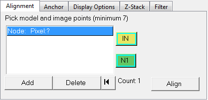 Figure 9. The points on the image and the corresponding nodes on the model should be as close and accurate as possible, in order to optimize the alignment and scaling. A minimum of seven points/nodes are required, however for this exercise we will select a total of nine points/nodes.Note: To enable the easy picking of nodes on the model, please make the image in the graphics window completely transparent by using the slider bar in the Display Options tab (sliding to High), or turn off the display of the Image plane from the Results browser tab. You can also adjust the color of the model, if necessary.
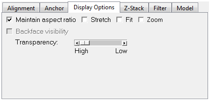 Figure 10.
 -
A set of nine node-point pairs that provided a good alignment with a very low
error value are shown in the images below. For the purpose of this exercise,
please try and select your points and nodes as closely as possible to those on
the images:
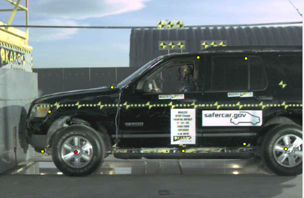 Figure 11. Image plane with 9 points selected
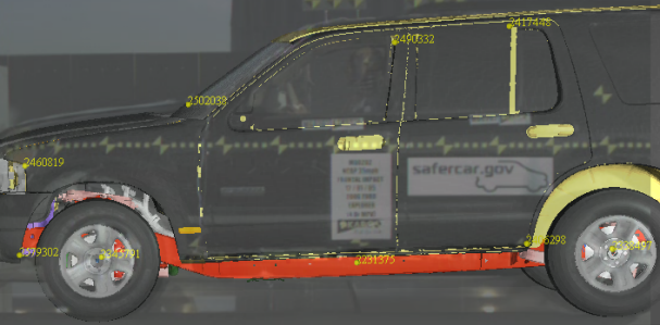 Figure 12. Model with 9 nodes selected
-
Next, select the middle of the front wheel as the first node on the
model (Node: #2345791).
The Alignment tab is populated with the first point and node pair.
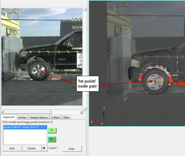 Figure 13.
-
Next, select the middle of the front wheel as the first node on the
model (Node: #2345791).
-
All user defined or image plane alignment generated views are locked by
default. Unlock the ImagePlane1 Model1 lens type view by
unchecking the Lock box (located in the Standard section of the Entity Editor).
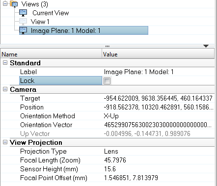 Figure 14.
 When a view is unlocked, it is also synchronized with the graphics window.
Import a Video as a 3D Object and Animate with the Model
-
Select the XZ Right Plane View
to align the h3d model and the avi file in the same plane.
-
Next activate the blue N2 selector, select the center
point of the right tire in the animation window, and then select
Done in the panel area.
When the two points have been selected, an arrow will be displayed going from N1 to N2.
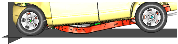 Figure 15.
 -
Next click the yellow IN2 selector to make it active,
and then select the center point on the right wheel.
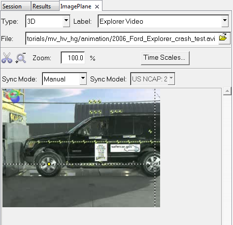 Figure 16.
 -
Click Align to align the two images.
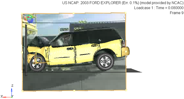 Figure 17.