Electronic Stability Program
During critical maneuvers, such as an obstacle avoidance, a vehicle can easily become uncontrollable due to excessive skidding. While performing a steering maneuver, especially at high speeds, significant lateral forces are acting on tires. These forces are responsible for the yaw moment acting on the vehicle which finally set its orientation. If these forces though reach their limit due to traction, the vehicle is unable to perform the desired maneuver and becomes unstable. For this reason, Electronic Stability Program (ESP) is introduced.
ESP is a driver assist system that improves vehicle’s stability through intervention in the braking system. By individual wheel braking ESP can control the yaw moment of the vehicle, thus its steering behavior.
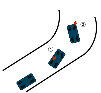
Figure 1. ESP Braking Action During Understeer or Oversteer
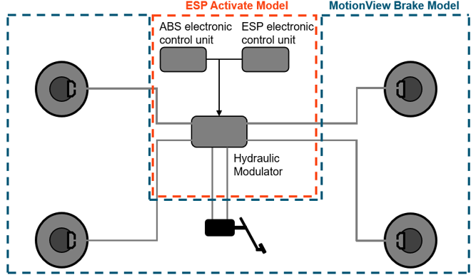
Figure 2. ESP Intervention in the Brake System
ESP Module in Activate
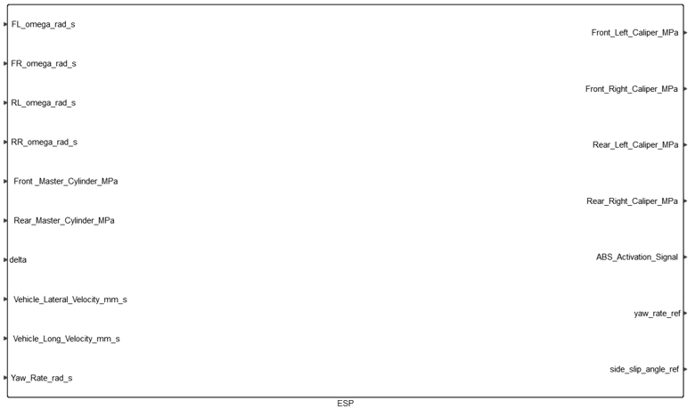
Figure 3. ESP Block in Activate
Some of the inputs represent signals from sensors (wheels velocities, vehicle long and lateral velocity, steering angle, yaw rate) while the rest are connecting the hydraulics parts from MotionView to the ones in Activate (Master cylinder pressure). Vehicle velocities are usually estimated rather than measured. In the current implementation these values were used as outputs from MBS vehicle model in order to focus on the control system’s behavior.
ESP Electronic Control Unit
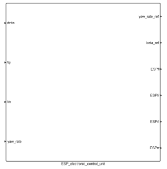
Figure 4. ESP Electronic Control Unit in Activate
- Yaw rate and side-slip angle reference value
- The reference yaw rate and side-slip angle values can be obtained by linearizing the
steady-state equations of motion of single-track vehicle model.
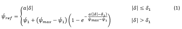
For the yaw rate reference value:
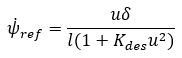
Where
 is
vehicle’s longitudinal velocity,
is
vehicle’s longitudinal velocity,  front
wheels steering angle,
front
wheels steering angle,  vehicle’s wheelbase and
  the
desired understeering coefficient. The actual understeer coefficient of the vehicle
can be calculated by the following formula:
the
desired understeering coefficient. The actual understeer coefficient of the vehicle
can be calculated by the following formula: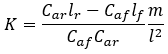
Where
 are front and rear axle cornering stiffness,
  are
distance of front and rear axle from the vehicle’s center of gravity and
are
distance of front and rear axle from the vehicle’s center of gravity and  is the vehicle’s mass.
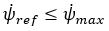
For the calculation of the yaw rate reference it is also important to take into consideration the upper bound of friction limit between tire and road.
For this reason
Where
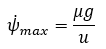
Where
 is the
friction coefficient between tire and road and
is the
friction coefficient between tire and road and  is
gravity’s acceleration.
is
gravity’s acceleration.So, the final yaw rate reference in order to avoid discontinuity can be calculated as shown below:
Where
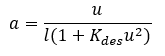
For the side-slip reference:
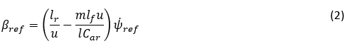 In Activate equations (1) and (2) can be implemented as shown below:
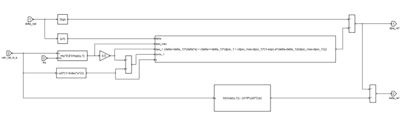
Figure 5. Yaw Rate and Side-Slip Angle Reference in ActivateFor the calculation of reference values, except from and signals
that come from MotionView, some parameters should also
be set in model initialization in Activate as shown
below: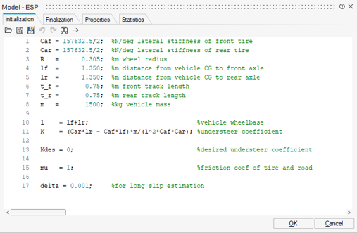
Figure 6. ESP Parameters in Activate - Control Law
- As mentioned before, ESP uses the error of the yaw rate and the side-slip angle to
generate the desired yaw moment for the vehicle. Thus, the control law can be
represented as a Proportional controller as shown below:
Where and
and
 are the proportional gains of the controller.
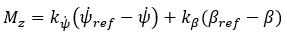
Figure 7. ESP Control Law in ActivateAs stated earlier, ESP’s actuator is the vehicle brake system. The desired yaw moment of the vehicle is created by individual wheel braking.
In case of understeering, the front axle is losing grip, therefore the rear wheel is braked while in case of oversteering, the rear axle is losing grip and the front wheel is braked. Thus, by having the turn’s orientation (left or right) and the understeer condition of the vehicle (understeer or oversteer) the optimal tire is selected for braking in order to produce the desired yaw moment. The tire selection algorithm as created in Activate is shown below: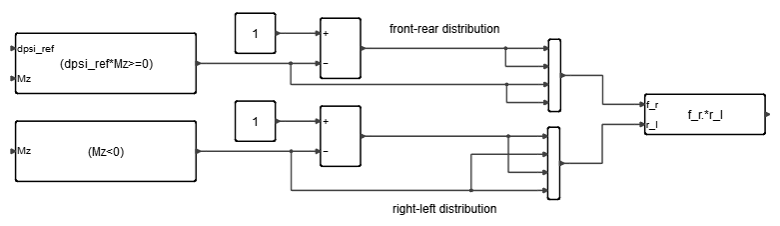
Figure 8. Tire Selection from ESP in ActivateThe desired yaw moment for the vehicle should be expressed in desired caliper pressure which will be then produced by the hydraulic modulator. The yaw moment is first expressed in longitudinal force on tire, by using the proper track width (front or rear). Then braking torque using tire’s radius and finally the braking pressure using brake systems parameters. Implementation in Activate is shown below: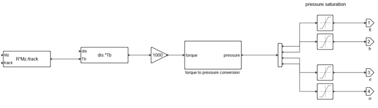
Figure 9. Yaw Moment to Brake Pressure in Activate - ABS
-
To prevent wheel lock during ESP’s braking, ABS, as a lower-level controller, monitors longitudinal slip. Just like in a braking condition, brake pressure is modulated by the ABS ECU through the hydraulic modulator so that the pressure can either increase, hold, or decrease. Additional information on ABS design logic and function can be found in the Anti-lock Braking System topic.
Create a Full Vehicle Model with ESP
- From the File menu, select .
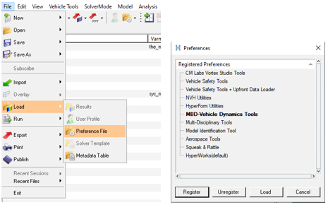
Figure 10. - From the Model menu, select Assembly Wizard.
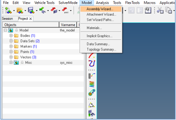
Figure 11. - Under Select ABS/ESP and TC an Electronic Stability
Program (ESP) option will be available for selection.
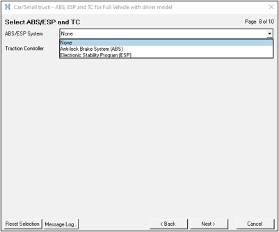
Figure 12. - Completing the Assembly Wizard's selections will lead to a full vehicle model with
Altair Driver and a Electronic Stability Program.
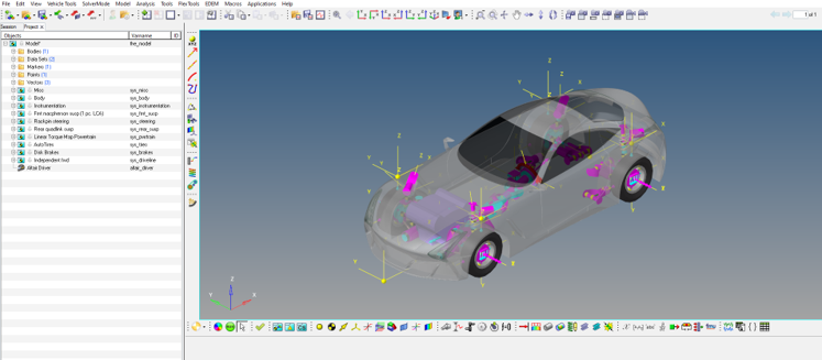
Figure 13.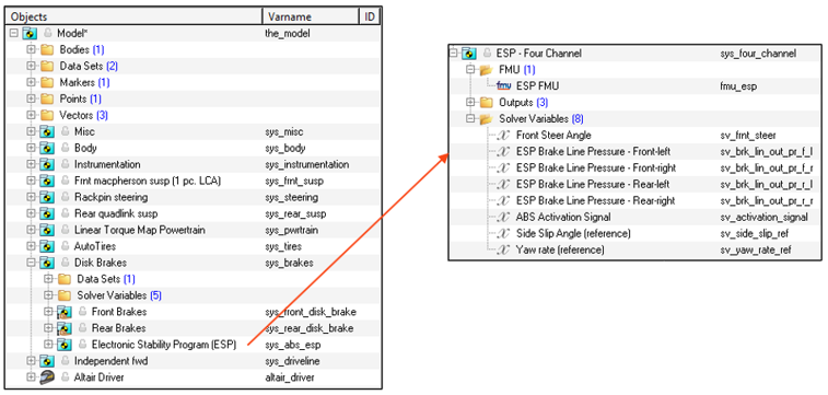
Figure 14.