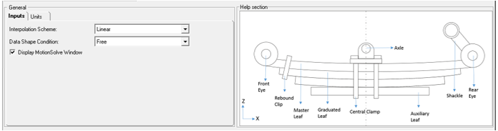
The General option in the tree browser provides basic details and displays the entire
model in the Help section. It is necessary for all the property files.
The information that has to be entered in the
Inputs and Units tabs are explained below. Figure 1. General Panel Section
Inputs
Interpolation Scheme
Defines the type of interpolation that is needed for the leaf profile.
For example, if you enter the leaf shape as 40 points, and opt to generate
10 beams on the front and 10 beams on the rear, the total number of profile
points required is 22. A function is needed to generate those points, but
that function requires an order and interpolation schemes.
Depending on the number of points, the interpolation scheme is predicted.
Large number of points: Linear
Two starting points: Quadratic
Three starting points: Cubic
Data Shape Condition
The Leaf Spring Builder builds leaf springs from two different kinds of
profile inputs or shape conditions.
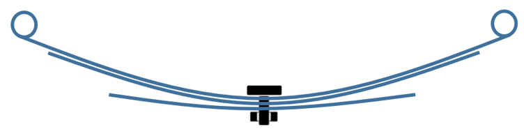
Free Shape Condition: In Free Shape
condition, an assembled leaf pack is generated. The leaf spring is
created with the center bolt represented as a fixed joint. The input
profiles of the leaves for this option will be the profiles as in a
leaf stack.
Note: The leaf pack is assembled in the pack but is NOT
installed in a vehicle, in other words, it is not deformed by
the vehicle weight.
Figure 2. Spring in Free Shape
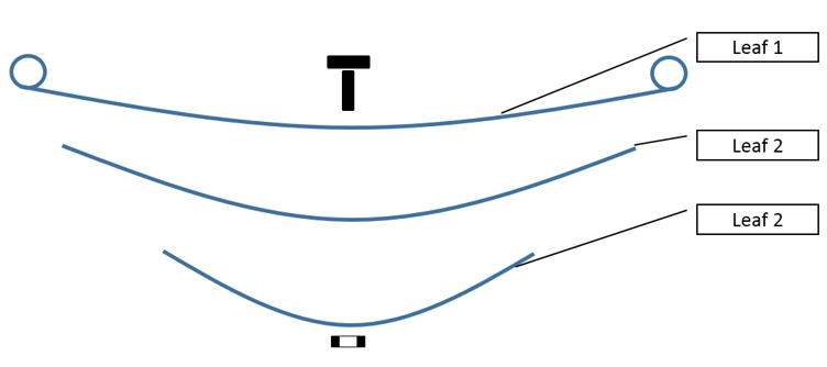
Pre-Assembly: In Pre-assembly, you have
individual leaf profiles for each leaf. These individual leaf
profiles can be bolted together with the assembling load. The
following image shows how the data of leaves are collected. If the
free shape data of each leaf is available, it is preferable to
create the leaf pack using this option. Figure 3. Spring in Pre-assembly Position
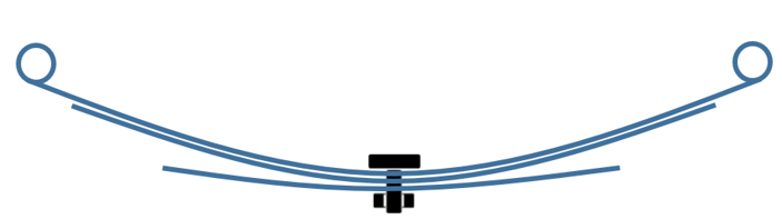
Design Assembly: In Design Assembly, an
assembled and loaded leaf spring pack is generated. You have an
assembled leaf spring pack installed in the vehicle with the actual
vehicle loads on it. The leaf spring will be generated with bolt
(Fixed Joint) and design load stored in the beam elements. The input
profiles for this option will be the leave profiles extracted from a
bolted and loaded leaf stack. See Assembled and Loaded Leaf Spring for additional
information. Figure 4. Spring in Free Shape Figure 5. Spring in Design Assembly
Shape Measurements
The Leaf Spring Builder
creates MotionView MDL leaf spring models which are only as good as the leaf shapes
input entered in the software. Therefore, accurately measuring the leaf shapes in the
required coordinate system is important. The coordinate system, its origin and
orientation need to follow certain rules to be useful in creating a leaf-spring from the
Leaf Spring Builder.
The following sections describe the coordinate systems and
measurement methods for the Free and Pre-Assembly shape conditions.
The
coordinate systems and measurement methods for Design and Free are the same as
discussed below.
Measuring a Leaf Spring in Free Shape
In Free Shape, the leaves are already assembled into a pack, but not
installed in the vehicle. All of the leaves together form a single unit.
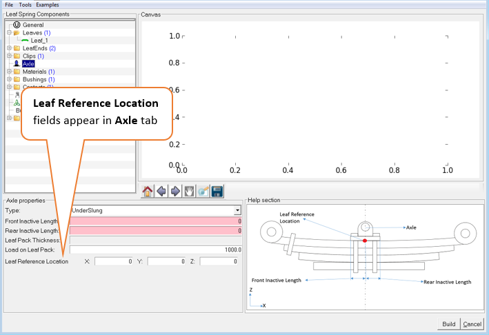
In this condition, the measurements need to be made in a consistent
coordinate system only. Also, it is necessary to input a correct Leaf
Reference Location under the Axle tab. The Leaf Reference Marker will be
created at this location. Figure 6. Leaf Reference Location in Axle Component Properties
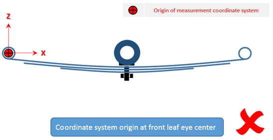
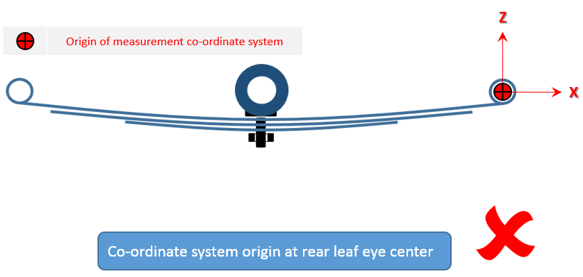
The following set of illustrations show the acceptable and unacceptable
selections of coordinate systems, its origins and orientations for leaf shapes.
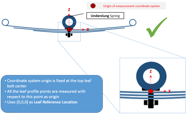
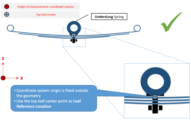
Acceptable Selections: Underslung Spring
Figure 7. Leaf Reference Location in Underslung-1 Figure 8. Leaf Reference Location in Underslung-2
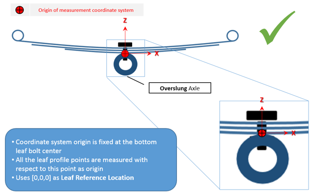
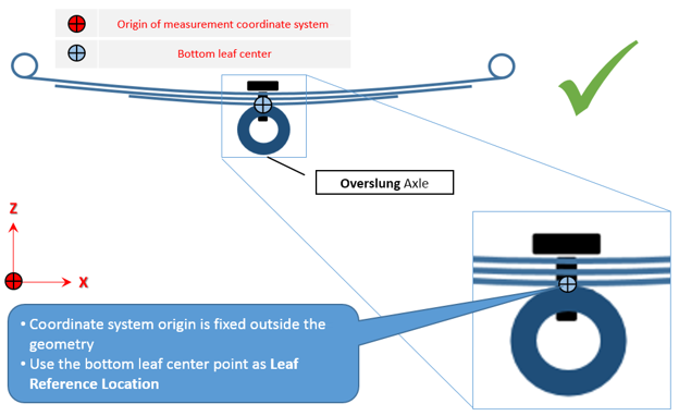
Acceptable Selections: Overslung Axle
Figure 9. Leaf Reference Location in Overslung-1 Figure 10. Leaf Reference Location in Overslung-2
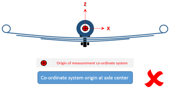
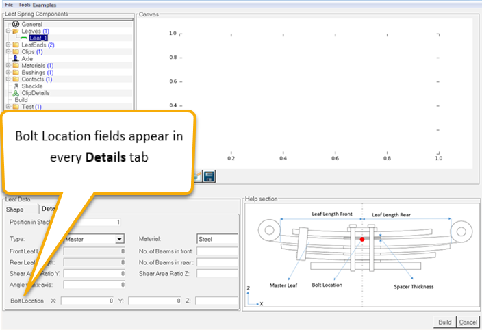
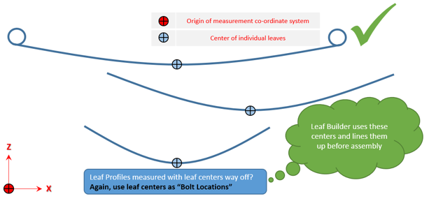
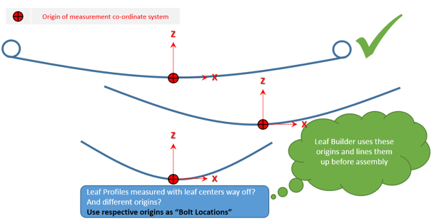
Leaves in the Pre-Assembly Shape condition are measured as independent
entities. A common coordinate system needs to be chosen for all the leaves. The Leaf
Builder takes an additional input called Bolt Location in the Pre-Assembly Shape
condition, which is used to line up the leaves along a common vertical axis before they
are bolted together in a MotionSolve simulation to create
the assembled leaf pack. Figure 15. Bolt Location in Leaf Details
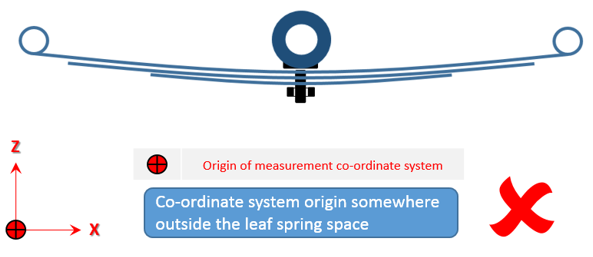
The following set of illustrations show acceptable and unacceptable selections
of coordinate systems, its origins and orientations of leaf shapes.
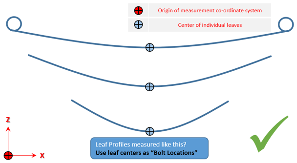
Acceptable Selections:
The bolt hole axis of each leaf must be parallel to every other leaf and
and to the Z-axis. The vertical locations of each leaf will be offset by
MotionSolve during assembly, such that
there is no contact between leaves. Figure 16. Acceptable Selection for Pre-Assembly-1 Figure 17. Acceptable Selection for Pre-Assembly-2 Figure 18. Acceptable Selection for Pre-Assembly-3
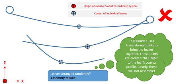
Unacceptable Selection:
Figure 19. Unacceptable Selection for Pre-Assembly-1
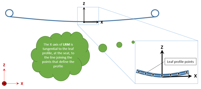
Leaf Reference Marker
The Leaf Reference
Marker (henceforth referred to as LRM in this section) is the coordinate system in which
all the points of the leaf profiles are created in MotionView. To move/orient a leaf spring, you can simply move and/or reorient the LRM.
It is
necessary during measurement to have all the leaves positioned such that the
tangents at the leaf centers (clamped portion of the leaves) are parallel. A visual
inspection of leaf positions on the measuring table is done to ensure this is
generally sufficient to get a good leaf spring out of the Leaf Builder. Figure 20. Leaf Reference Marker Location
The Leaf Reference Marker is created at one of the following locations
based on shape condition:
Free Shape: Leaf Reference Location as input by the user, Top leaf center
for Underslung spring and Bottom leaf center for Overslung spring.
Pre-Assembly Shape: Top leaf bolt location for Underslung spring and Bottom
leaf bolt location for Overslung spring.
The Leaf Builder uses the Leaf Reference Marker-origin (location) as the
point where the Axle is attached.
General Inputs for Leaf Property File (*lpf)
In the General Inputs block of a Leaf Property file, the attribute, type, and valid
value to be entered in TiemOrbit file format are detailed in the following table.
This table also provides information about the mandatory requirements for
attributes. An example of how a General Inputs block is represented in a TiemOrbit
file format is shown
below:
If there are none, then “ZERO” has to be
mentioned.
Yes
shapeCondition
String
'FREE'
'PRE_ASSEMBLY'
Yes
outputFileLabel
String
File_label
Yes
dispMsolveWindow
String
'TRUE, 'FALSE''
Yes
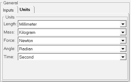
Units
Units are required for all types of the data files to be read by the builder. It
specifies the length, mass, force, angle, and time units employed in the file.
Currently, you will have to use the default units and have no control over
units. Figure 21. General - Units Tab
Units for Leaf Property File (*lpf)
In the units block of Leaf Property file, the dimension, options, and conversion
factors to be used are detailed in the following table. An example of how a Units
block is represented in a TiemOrbit file format is shown
below.
$---------------------------------------------------------UNITS
[UNITS]
(BASE)
{LENGTH	   FORCE       ANGLE       MASS         TIME}
MILLIMETER	NEWTON      RADIAN      KILOGRAM     SECOND