Stability Analysis
The Stability Analysis event can be used to simulate two-wheeler models on various road surfaces to evaluate the weave and wobble modes of the vehicle. A user-defined road property file determines the road input.
Adding the Event to a Two-Wheeler
- Right-click on Model in the browser and select Add
Events.
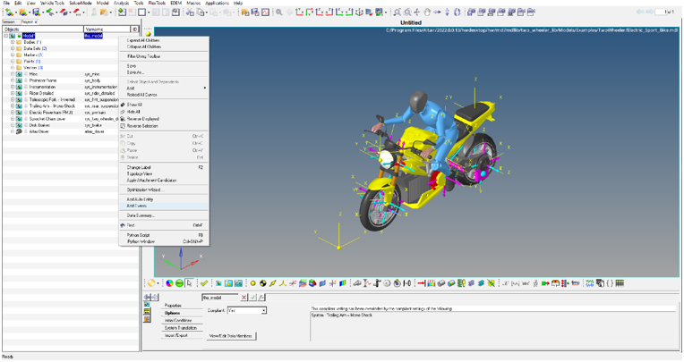
Figure 1. - From the Add Events dialog, select Stability Analysis from the
Type drop-down menu and click Apply.
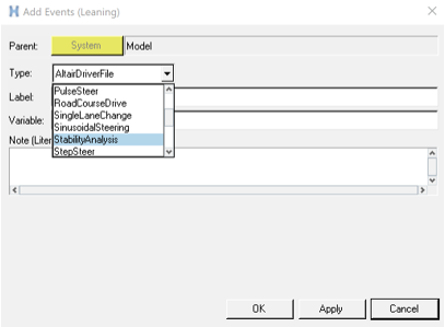
Figure 2.The Stability Analysis event is added to the model.
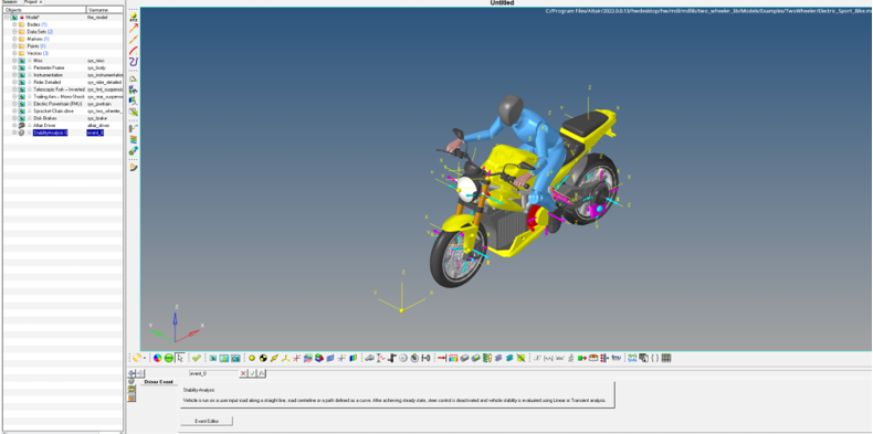
Figure 3.
Panel Options
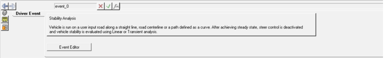
Figure 4.
| Event Editor | Brings up the Event Editor dialog. |
Browser Context Menu Options
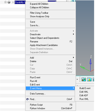
Figure 5.
| Run Event | Runs the event (exports XML, ADF and submits the solver input file to MotionSolve). |
| Run All | Runs all of the full vehicle events added in the model. |
| Edit Event | Brings up the event setting dialog/Event Editor. |
| Build Event | Exports the solver input file and ADF file to the path provided in the Event Editor dialog. |
| Edit XML | Opens the XML in text editor. |
| Edit ADF | Opens the ADF text editor. |
| Run XML | Submits the solver input file (if generated) to MotionSolve. |
Dialog Options
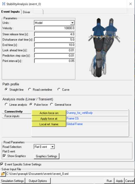
Figure 6.
| Units | Unit of constant demand velocity input. |
| Velocity | Constant demand velocity input. |
| Steer release time [s] | Used in the Pulse force and General force analysis mode. Time at which
steer control is released.
Note: For the Linear analysis
mode, the steer control is released at the end time and a Linear analysis is
run.
|
| Disturbance start time [s] | Used in the Pulse force analysis mode. Start time for the pulse force disturbance defined in the Force inputs tab. |
| End time [s] | End time for the simulation. |
| Look ahead time [s] | Steer controller (FEEDFORWARD) input for driver. |
| Prediction step size [s] | Steer controller (FEEDFORWARD) input for driver. |
| Print interval [s] | Print interval for the results (.mrf). |
| Path profile - Straight Line | The vehicle follows a straight line. |
| Path profile - Road centerline | The vehicle follows the road centerline (Road centerline is generated in a DDF file before the start of the simulation). |
| Path profile - Curve |
Option to attach a MotionView x-y curve as the path
input.
|
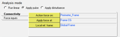
| Analysis mode - Linear analysis | Option for running linear analysis at the end of the simulation after steer control is deactivated. |
| Analysis mode - Pulse force |
Option for running transient analysis after deactivating the steer control at Steer release time to End time with disturbance applied at Disturbance start time. Body, point, and reference frame for the disturbance force can be defined in the Connectivity tab.
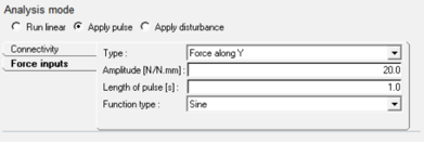
Type of force can be chosen from Force along Y or Torque about Z. These are typical cases where disturbance is caused by applying lateral force on the frame or steering torque is applied about steering revolute joint. Amplitude, Length of pulse, and Function type can be defined describing the pulse force like the Pulse steer event.
|
| Analysis mode - General force |
Option for running transient analysis after deactivating the steer control at Steer release time to End time. Body, point, and reference frame for the disturbance force can be defined in the Connectivity tab. Disturbance can be defined using MotionSolve expressions in six directions using the Trans Properties and Rot properties tabs.
|
Run a Stability Analysis Event
- Build a full vehicle model with Altair Driver.
- Add a Stability Analysis event.
- Open the Event Editor dialog.
- Provide a road profile (Straight/Road centerline/Curve) and analysis mode (Linear force/Pulse force/General force) inputs.
- Resolve attachments for the disturbance and define the disturbance force, if needed.
- Edit other event related parameters.
- Enter the solver input file location.
- Edit the driver output settings, simulation settings, and output options for simulation.
- Click the Run button to start the simulation.