Constructing the Spiral Antenna
Create the complementary slotted two-arm spiral antenna in CADFEKO.
-
Create a helix.
- Definition method: Base centre, base radius, end radius, height, turns
- Origin of the helix (C): (0, 0, 0)
- Base radius (Rb): r1
- End radius (Rt): r2
- Height: 0
- Turns (N): n
- Label: Helix1
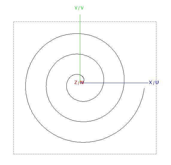
Figure 1. Top view of Helix1. -
To add width to the spiral, create a copy (duplicate) of
Helix1.
-
Modify the start radius and end radius:
- Base radius (Rb): r1 + w
- End radius (Rt): r2 + w
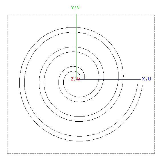
Figure 2. Top view of Helix1 and Helix2.
-
Modify the start radius and end radius:
-
Connect the two helices to create a surface (loft).
-
Select Helix1 and Helix2 and loft
the two curves to create a surface.
Note: Do not select the Reverse orientation check box.
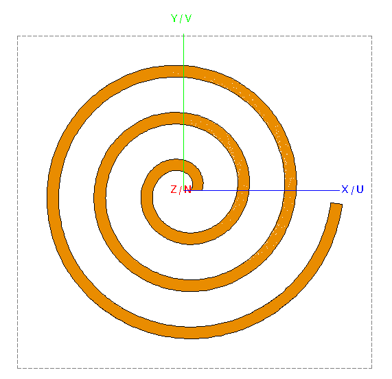
Figure 3. Top view of the lofted surface (spiral).
-
Select Helix1 and Helix2 and loft
the two curves to create a surface.
-
Create half of the feed.
-
Create a polygon.
- Corner 1: (r1 + w/2, -w/2, 0)
- Corner 2: (0, -w/2, 0)
- Corner 3: (0, w/2, 0)
- Corner 4: (r1 + w/2, w/2, 0)
- Corner5: (r1 + w, 0, 0)
- Label: Polygon1
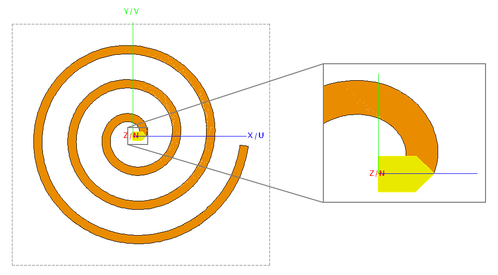
Figure 4. Top view of the lofted surface (spiral) showing half of the feed at the centre.
-
Create a polygon.
-
Create the second arm of the spiral antenna.
-
Copy and rotate Union1 by 180° around the N 軸.
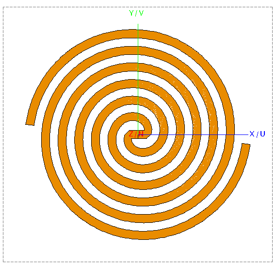
Figure 5. Top view of the two-arm spiral.
-
Copy and rotate Union1 by 180° around the N 軸.
-
Create the spiral slots in the conductive plate.
-
Subtract Union2 from
Rectangle1.
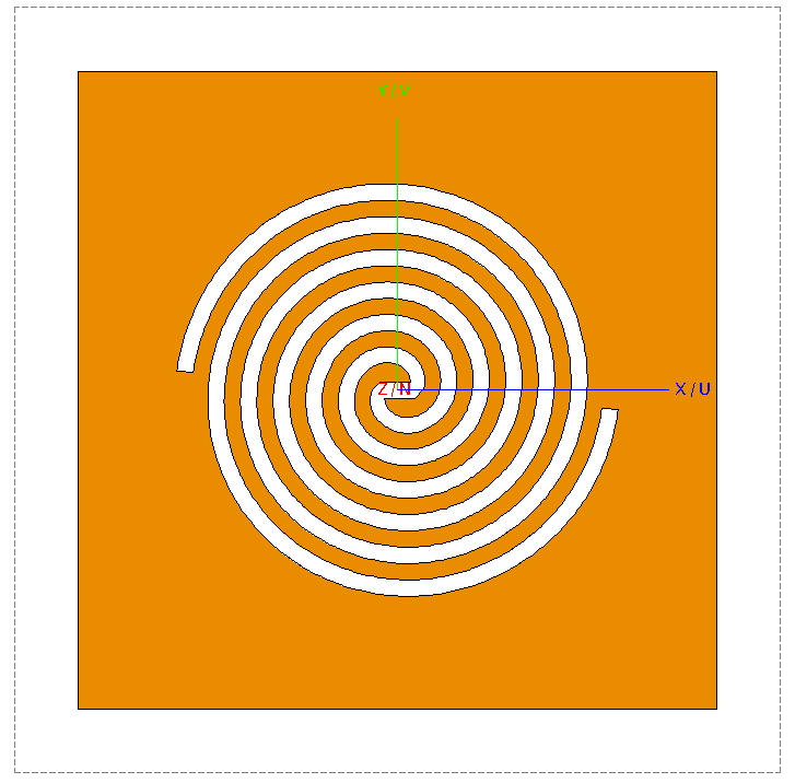
Figure 6. Top view of the two-arm spiral slots in a conductive plate.
-
Subtract Union2 from
Rectangle1.
-
Add a wire port to the feed wire.
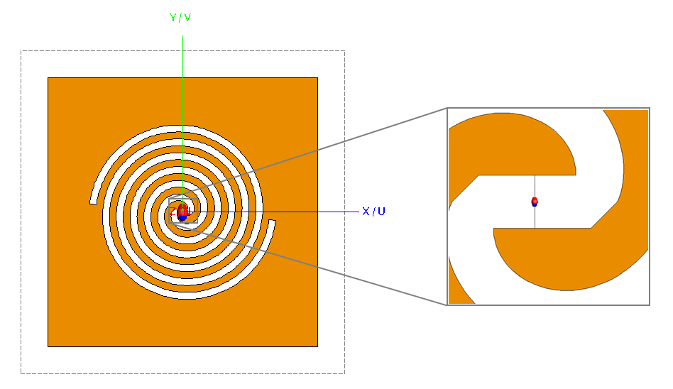
Figure 7. Top view of the complementary two-arm slot antenna showing the wire port at the feed line.