CADFEKO and POSTFEKO have a powerful, fast, lightweight scripting language integrated into the application that allows you to create models,
get hold of simulation results and model configuration information and much more.
The MLFMM is an iterative solution method, and under certain conditions, the iterative solution may fail to converge. Several
model or solution settings are presented that could improve the model's convergence behaviour.
The hybrid マルチレベル高速多重極法 (MLFMM) / 有限要素法 (FEM) is an iterative solution method and under certain conditions, the iterative solution may fail to converge.
Several model or solution settings are presented that could improve the model's convergence behaviour.
The hybrid モーメント法 (MoM) / 有限要素法 (FEM) is an iterative solution method, and under certain conditions, the iterative solution may fail to converge.
Several model or solution settings are presented that could improve the model's convergence behaviour.
The 時間領域差分法 (FDTD) is a solution method that may fail to converge under certain conditions. Several model or solution settings
are presented that could improve the model's convergence behaviour.
When meshing a model, you can either use the automatic meshing algorithm to calculate the appropriate mesh settings
or you can specify the mesh sizes. When you specify the mesh sizes, the mesh sizes should adhere to certain guidelines.
Feko integrates with various products within Altair Simulation Products such as HyperStudy. Integration with third-party products is also supported through the powerful scripting and plug-in infrastructure.
Feko creates and uses many different file types. It is useful to know what is stored in the various files and weather they were
created by Feko and if it is safe to delete them. The files are grouped as either native files that have been created by Feko or non-native files that are supported by Feko. Non-native files are often exported by Feko even if the formats are not under the control of the Feko development team.
Different configurations using a microstrip port are considered.
The first configuration considered is to define a microstrip port on the full width of
the microstrip line. For the second and third configurations, a feed structure is
created using polygons to decrease the width of the microstrip port.
Narrow Version
To decrease the width of the microstrip port, a polygon is added to the microstrip
line to act as the feed structure. For better accuracy, ensure that the width of the
microstrip port is roughly of the microstrip line width.
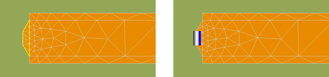