OS-V: 0270 Torsional Creep of Circular Shaft

This benchmark illustrates the structural response of a power law creeping material in a geometrical configuration subjected to pure torsion. OptiStruct examines strain at the edge of the shaft.

The model examines the torsional creep in circular shaft with 2 variations:
  • Relaxation at constant twist
  • Forward creep at steady twist rate

Relaxation at Constant Twist

Twist is applied to the shaft and remains constant from 0 to 100s. Total strain and creep strains then analyzed.


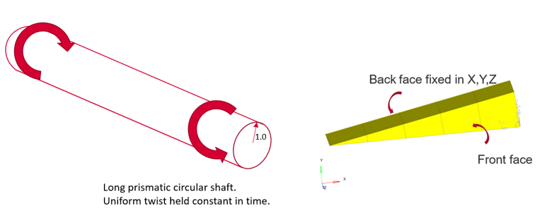
図 1. Model and Loading Description

Benchmark Model

Four 20-noded brick elements, plus one 16-noded wedge are used. All nodes on lower face are fixed in X, Y, Z.
  • X, Y displacements given at all nodes of front face using cylindrical system: 0.002 mm
  • Rotation is given at mid-side nodes: 0.001 radians

Uniform twist of 0.01 radians/unit length is held constant in time from 0 to 100s.

Twist is instantaneously applied to the shaft and then maintained constant. The initial response is elastic and subsequently the structure response with a progressive accumulation of creep strain. Stress reduces (relaxes) slowly till 100s due to creep.
Material Properties
Value
Young's modulus
10 GPa
Poisson's ratio
0.3
Creep law equation
ε ˙ eq =1000  σ 5 eq MathType@MTEF@5@5@+= feaagKart1ev2aaatCvAUfeBSjuyZL2yd9gzLbvyNv2CaerbuLwBLn hiov2DGi1BTfMBaeXatLxBI9gBaerbd9wDYLwzYbItLDharqqtubsr 4rNCHbGeaGqiVu0Je9sqqrpepC0xbbL8F4rqqrFfpeea0xe9Lq=Jc9 vqaqpepm0xbba9pwe9Q8fs0=yqaqpepae9pg0FirpepeKkFr0xfr=x fr=xb9adbaqaaeGaciGaaiaabeqaamaabaabaaGcbaGafqyTduMbai aadaWgaaWcbaGaamyzaiaadghaaeqaaOGaeyypa0JaaGymaiaaicda caaIWaGaaGimaiaabccacqaHdpWCdaahaaWcbeqaaiaaiwdaaaGcda WgaaWcbaGaamyzaiaadghaaeqaaaaa@4313@
Where,
ε ˙ eq MathType@MTEF@5@5@+= feaagKart1ev2aaatCvAUfeBSjuyZL2yd9gzLbvyNv2CaerbuLwBLn hiov2DGi1BTfMBaeXatLxBI9gBaerbd9wDYLwzYbItLDharqqtubsr 4rNCHbGeaGqiVu0Je9sqqrpepC0xbbL8F4rqqrFfpeea0xe9Lq=Jc9 vqaqpepm0xbba9pwe9Q8fs0=yqaqpepae9pg0FirpepeKkFr0xfr=x fr=xb9adbaqaaeGaciGaaiaabeqaamaabaabaaGcbaGafqyTduMbai aadaWgaaWcbaGaamyzaiaadghaaeqaaaaa@39B2@
Equivalent creep strain rate
σ eq MathType@MTEF@5@5@+= feaagKart1ev2aaatCvAUfeBSjuyZL2yd9gzLbvyNv2CaerbuLwBLn hiov2DGi1BTfMBaeXatLxBI9gBaerbd9wDYLwzYbItLDharqqtubsr 4rNCHbGeaGqiVu0Je9sqqrpepC0xbbL8F4rqqrFfpeea0xe9Lq=Jc9 vqaqpepm0xbba9pwe9Q8fs0=yqaqpepae9pg0FirpepeKkFr0xfr=x fr=xb9adbaqaaeGaciGaaiaabeqaamaabaabaaGcbaGaeq4Wdm3aaS baaSqaaiaadwgacaWGXbaabeaaaaa@39C5@
Equivalent stress (Mises)

Nonlinear Static Analysis Results

An implicit visco-elastic solution method was used. Displacement, total strain and creep strain results are analyzed at the edge of the shaft at 100s.
OptiStruct NAFEMS Normalized Target Value
Total Strain (*10-3) 5.46 5.77 0.95
Creep Strain (*10-3) 4.85 4.77 1.01
Comparison of strain plots.


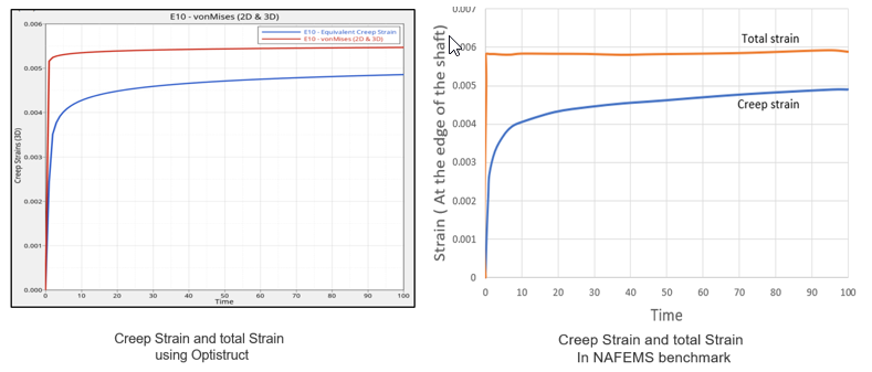
図 2. Comparison of Total Strain and Creep Strain at the Edge of the Shaft

Model Files

必要なモデルファイルのダウンロードについては、モデルファイルへのアクセスを参照してください。

The model file used in this example includes:

Torsional_Creep_Relaxation_at_constant_twist.fem

Forward Creep at Steady Twist Rate

A steadily increasing twist is applied at constant rate to the shaft.

The stresses increase from zero to steady value. The loads, which cause this steady-state behavior are referred as “primary” loads.

This model is the same as used in Relaxation at Constant Twist; except the boundary conditions.


図 3. Model and Loading Description

Benchmark Model

Four 20-noded brick elements, plus one 16-noded wedge are used. All nodes on lower face are fixed in X, Y, Z.
  • X, Y displacements given at all nodes of front face using cylindrical system: 0.004 mm/unit time
  • Rotation is given at mid-side nodes: 0.002 radians/unit time
Uniform twist of 0.02 radians/unit time is steadily increating with time from 0 to 1.5 applied using table curve.
Material Properties
Value
Young's modulus
10 GPa
Poisson's ratio
0.3
Creep law equation
ε ˙ e q = 1000   σ 5 e q MathType@MTEF@5@5@+= feaagKart1ev2aaatCvAUfeBSjuyZL2yd9gzLbvyNv2CaerbuLwBLn hiov2DGi1BTfMBaeXatLxBI9gBaerbd9wDYLwzYbItLDharqqtubsr 4rNCHbGeaGqiVu0Je9sqqrpepC0xbbL8F4rqqrFfpeea0xe9Lq=Jc9 vqaqpepm0xbba9pwe9Q8fs0=yqaqpepae9pg0FirpepeKkFr0xfr=x fr=xb9adbaqaaeGaciGaaiaabeqaamaabaabaaGcbaGafqyTduMbai aadaWgaaWcbaGaamyzaiaadghaaeqaaOGaeyypa0JaaGymaiaaicda caaIWaGaaGimaiaabccacqaHdpWCdaahaaWcbeqaaiaaiwdaaaGcda WgaaWcbaGaamyzaiaadghaaeqaaaaa@4313@
Where,
ε ˙ e q MathType@MTEF@5@5@+= feaagKart1ev2aaatCvAUfeBSjuyZL2yd9gzLbvyNv2CaerbuLwBLn hiov2DGi1BTfMBaeXatLxBI9gBaerbd9wDYLwzYbItLDharqqtubsr 4rNCHbGeaGqiVu0Je9sqqrpepC0xbbL8F4rqqrFfpeea0xe9Lq=Jc9 vqaqpepm0xbba9pwe9Q8fs0=yqaqpepae9pg0FirpepeKkFr0xfr=x fr=xb9adbaqaaeGaciGaaiaabeqaamaabaabaaGcbaGafqyTduMbai aadaWgaaWcbaGaamyzaiaadghaaeqaaaaa@39B2@
Equivalent creep strain rate
σ e q MathType@MTEF@5@5@+= feaagKart1ev2aaatCvAUfeBSjuyZL2yd9gzLbvyNv2CaerbuLwBLn hiov2DGi1BTfMBaeXatLxBI9gBaerbd9wDYLwzYbItLDharqqtubsr 4rNCHbGeaGqiVu0Je9sqqrpepC0xbbL8F4rqqrFfpeea0xe9Lq=Jc9 vqaqpepm0xbba9pwe9Q8fs0=yqaqpepae9pg0FirpepeKkFr0xfr=x fr=xb9adbaqaaeGaciGaaiaabeqaamaabaabaaGcbaGaeq4Wdm3aaS baaSqaaiaadwgacaWGXbaabeaaaaa@39C5@
Equivalent stress (Mises)

Nonlinear Static Analysis Results

An implicit visco-elastic solution method was used. Displacement, total strain and creep strain results are analyzed at the edge of the shaft at 1.5s.
OptiStruct NAFEMS Normalized Target Value
Total Strain (*10-2) 1.62 1.7321 0.94
Creep Strain (*10-2) 1.27 1.1693 1.094
Comparison of strain plots.


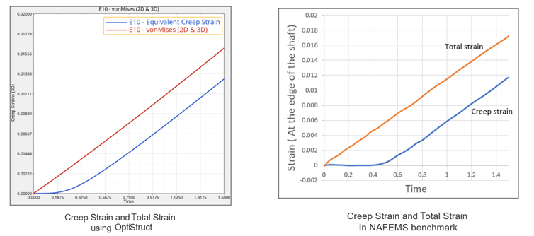
図 4. Comparison of Total Strain and Creep Strain at the Edge of the Shaft

Model Files

必要なモデルファイルのダウンロードについては、モデルファイルへのアクセスを参照してください。

The model file used in this example includes:

Torsional_forward_creep_at_steady_twist_rate.fem

Reference

NAFEMS R0026 - Selected Benchmarks for Material Non-Linearity- Volume 1