MV-1029: Model a Point-to-Deformable-Surface Force (PTdSF)
In this tutorial you will learn how to model a PTdSF (point-to-deformable-surface) joint with a contact force.
Create Points
In this step you will create the points necessary for the PTdSF force model.
-
Open the Add Point or PointPair dialog in one of the
following ways:
- From the Project Browser right-click on Model and select .
- On the Model-Reference toolbar, right-click the
 (Point) icon.
Create Bodies
In this step, you will create membrane and ball bodies for the PTdSF force model.
-
Open the Add Body or BodyPair dialog in one of the
following ways:
- From the Project Browser right-click on Model and select .
- On the Model-Reference toolbar, right-click on the
 (Body) icon.
-
Click the
 (Graphic file browser) icon and select
Plate.h3d from the <working
directory>.
(Graphic file browser) icon and select
Plate.h3d from the <working
directory>.
-
Double click
 .
.
Create Markers and a Deformable Surface
In this step you will define markers for the membrane.
-
On the general toolbar, click .
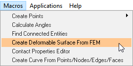
Figure 1. -
In the Deformable Surface from FEM panel, double-click
 .
.
-
Double-click on
 .
.
-
Next to Select the FEM file, click the (file
browser) icon.
-
Select the membrane.fem file from your working directory
and click OK.
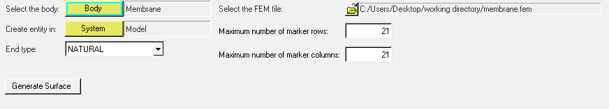
Figure 2.
Create Joints
In this step you will define the fixed joints between the membrane and the ground.
-
Open the Add Joint or JointPair dialog in one of the
following ways:
- From the Project Browser, right-click on Model and select .
- On the Model-Constraint toolbar, click the
 (Joints) icon.
-
In the Joint panel, configure the Connectivity tab.
-
Double-click
 .
.
- In the dialog, select Membrane and click OK.
-
Double-click
 .
.
- In the dialog, select Ground Body and click OK.
-
Double-click .
- In the dialog, select PointMembInterface39 and click OK.
-
Double-click
Create Contact
In this step you will define the contact force between the deformable membrane and the ball.
-
Open the Add Contact dialog in one of the following ways:
- From the Project Browser, right-click on Model and select .
- On the Model-Force toolbar, click the
 (Contacts) icon.
- In the dialog, for Label enter Contact 0.
- From the Type drop-down menu, choose PointToDeformableSurfaceContact. Then click OK.
-
From the Contact panel, configure the Connectivity tab.
-
Double-click on and select Ball.
Then click OK.
-
Double-click on and select BallCM.
Then click OK.
-
Double-click on
 and select DeformableSurface
1. Then click OK.
and select DeformableSurface
1. Then click OK.
-
Double-click on
-
Configure the Properties tab.
- For Radius, enter 10.
- For Stiffness, enter 1000.
- For Damping, enter 0.2.
- Uncheck the Flip normal check box.
Create Graphics
In this step, you will create a graphic for the ball.
-
Open the Add Graphics or GraphicPair dialog in one of the
following ways:
- From the Project Browser, right-click on Model and select .
- On the Model-Reference toolbar, click the
 (Graphics) icon.
- In the dialog, for Label enter Ball.
- In the Type drop-down menu, choose Sphere. Then click OK.
-
In the Connectivity tab, double-click .
- In the dialog, select Ball and click OK.
-
Double-click on .
- In the dialog, select BallCM and click OK.
- In the Properties tab, under Radius enter 10.
- In the Visualization tab, choose a color for the graphic.
Find Nodes
-
On the reference toolbar, click the (Bodies) icon.
-
Close the dialog.
Your model should look like the example given in Figure 3.
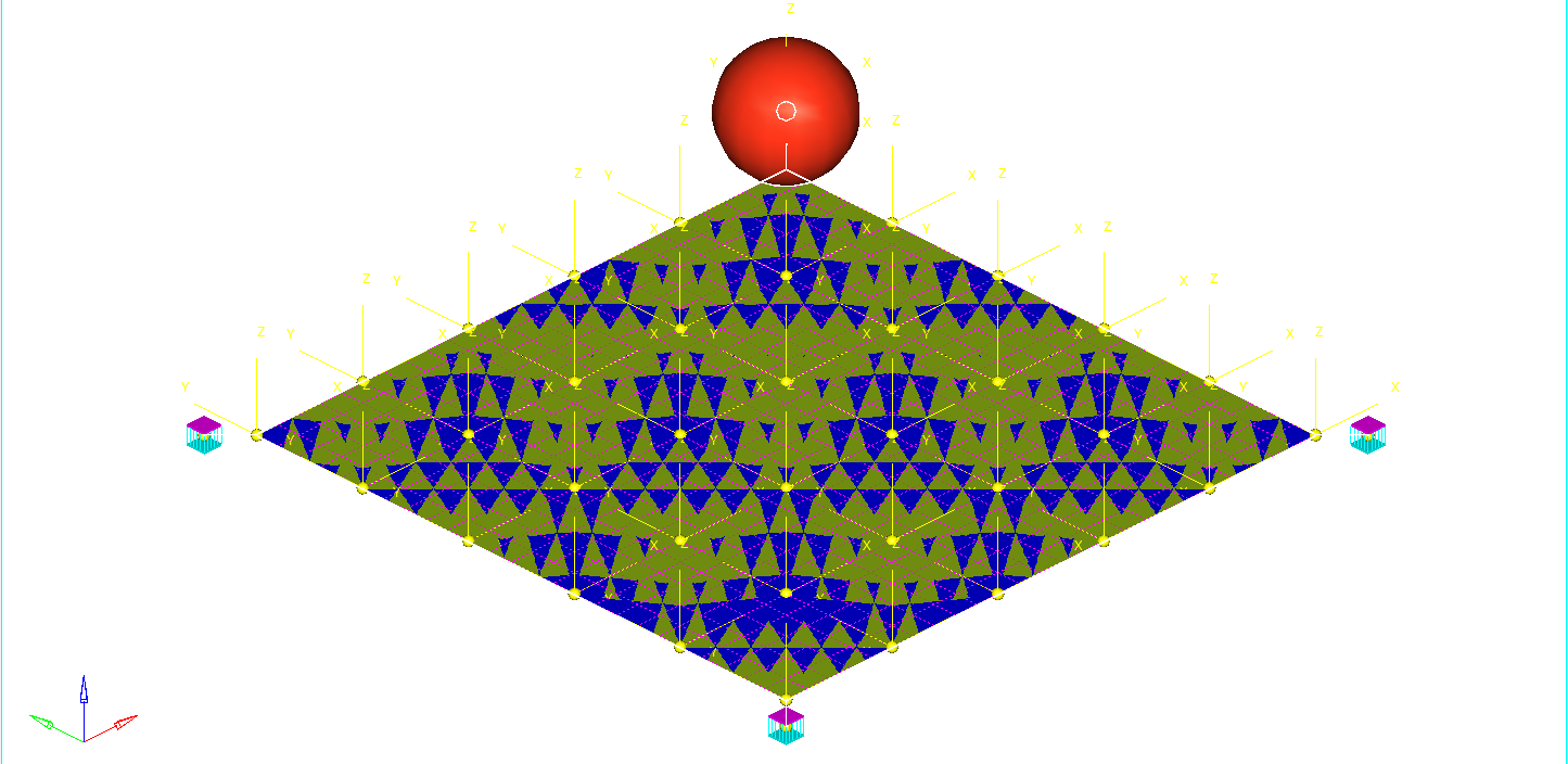
Figure 3.
Run the Model
-
On the toolbar, click
 (Run).
-
In the Run panel, specify the values shown in Figure 4.
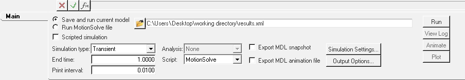 Figure 4.
 -
Click the
 (browser icon) and specify
result.xml as the name for the solver file.
(browser icon) and specify
result.xml as the name for the solver file.
-
Click the
 (Check Model) button to check the model for
errors.
(Check Model) button to check the model for
errors.
View the Results
In this step, you will view the animation and plot the Z position of the center of mass of the ball and the penetration distance for this flexible contact.
-
Once the solver has finished, the Animate button will be active. Click on
Animate.
Click the
 (Start/Pause Animation) button
to view the animation.
(Start/Pause Animation) button
to view the animation.One would also like to inspect the displacement profile of the membrane and the ball. For this, we will plot the Z position of the center of mass of the ball.
-
In the panel, make selections for the plot as shown in Figure 5.
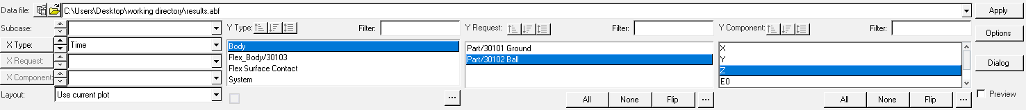
Figure 5. -
Click Apply.
The profile for the Z-displacement of the ball should look like the example given in Figure 6.
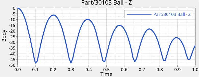
Figure 6. -
Click
 to add a new page to the session.
-
In the panel, select the options for the plot shown in Figure 7.
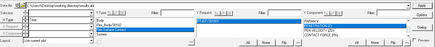
Figure 7.The penetration profile as a function of time should look like the example given in Figure 8.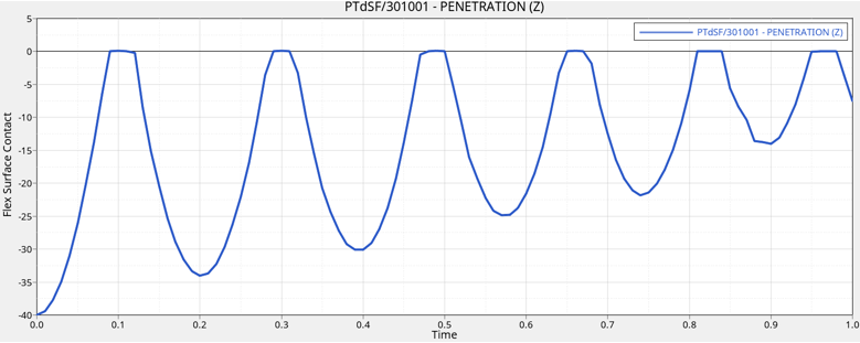
Figure 8.