OS-E: 0100 Nonlinear Analysis of Cantilever Beam
A cantilever beam undergoing large deflections is conducted and compared with 2D shell and 3D solids elements here, using OptiStruct.
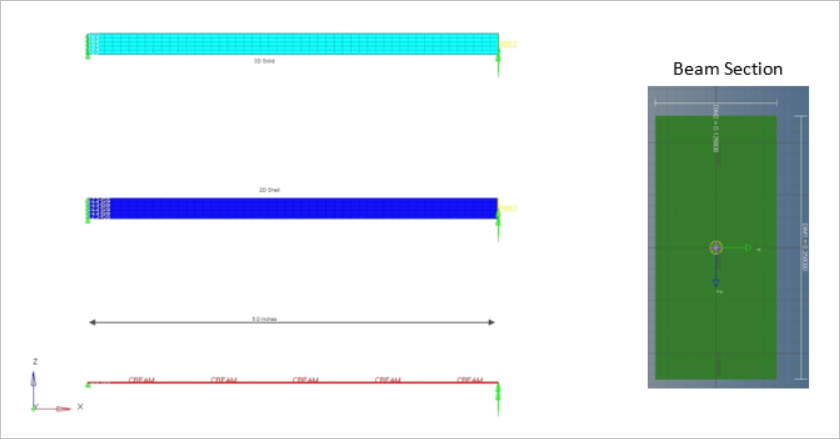
Figure 1. FE Model
Model Files
Refer to Access the Model Files to download the required model file(s).
The model file used in this example includes:
BEAM-LGDISP.fem
Model Description
The beam cross-section is modeled as an idealized section to compare with the assumptions of the analytical solution.
The loading is assumed to be applied through the centroid of the element cross-section (the neutral axis). This model also has 2D Shell and 3D hexa beam for comparison purpose only. The objective is to find the maximum magnitude of the displacement of the cantilever beam undergoing moment load of 100 lb*in z-axis, as shown in Figure 1.
- Young's Modulus
- 30E6 MPa
- Poisson's Ratio
- 0.3
Results
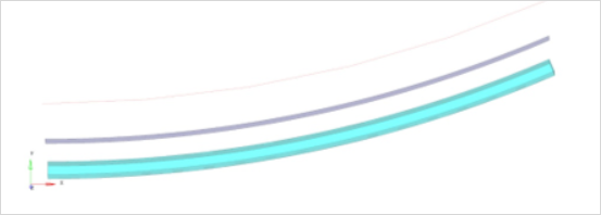
Figure 2. Deformation
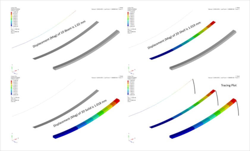
Figure 3. Displacement Contour