OS-SL-T: 1000 Nonlinear Analysis of Rubber Ring
This tutorial demonstrates the creation of finite elements on a given CAD geometry of a rubber ring.
Application of boundary conditions and a finite element analysis of the problem are explained. Post-processing tools are used to determine stress developed during crushing and sliding of a rubber ring.
The following exercises are included:
- Set up the problem in SimLab
- Apply Loads and Boundary Conditions
- Solve the job
- View the results
Launch SimLab
Launch SimLab.
Import the Model
Create Solution
-
In the Create Solution dialog, define the following
options:
-
For Select bodies, select all the bodies from the Model Browser and click OK.
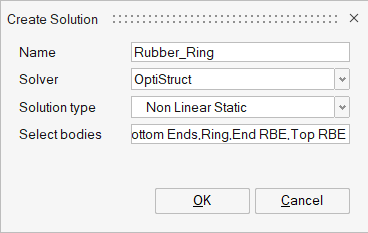
Figure 1. Solution Creation
-
For Select bodies, select all the bodies from the Model Browser and click OK.
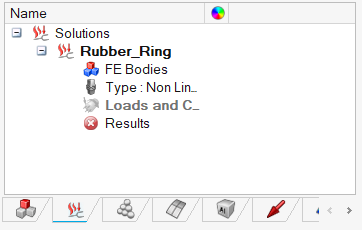
Figure 2. Solution defined in Solutions Browser
Set up the Model
Import Material
-
Enter the values, as shown below and click OK.
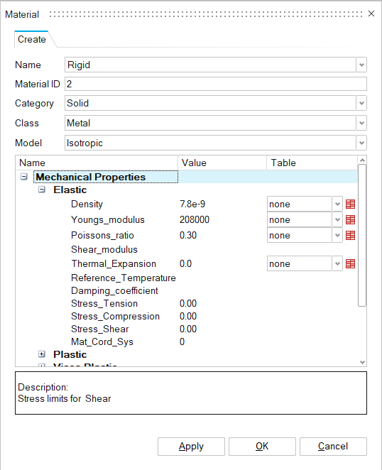
Figure 3. Creating Rigid Material
Create Properties
-
In the Analysis Property dialog, enter the values shown
below.
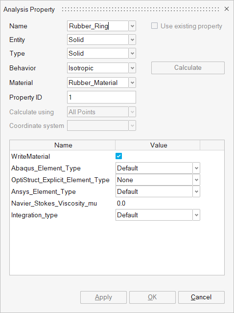
Figure 4. Create Rubber_Ring Property -
Assign property to Ring.
- In the Assembly tab of the Model Browser, select Ring.
- In the Analysis Property dialog, click Apply.
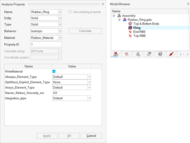
Figure 5. Assign Property to Ring -
Create a property for Top and Bottom Ends.
- Enter the values in the Analysis Property dialog, as shown below.
- In the Assembly tab of the Model Browser, select Top & Bottom Ends.
- In the Analysis Property dialog, click Apply.
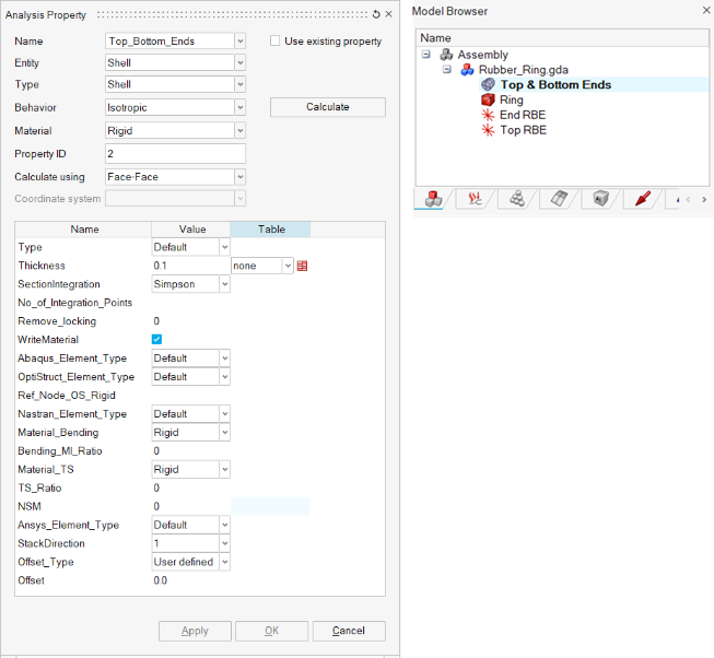
Figure 6. Assign Property to Top & Bottom End -
Create property for RBEs.
- Enter the values in the Analysis Property dialog, as shown below.
- In the Assembly tab of the Model Browser, select Top RBE and End RBE.
- In the Analysis Property dialog, click Apply.
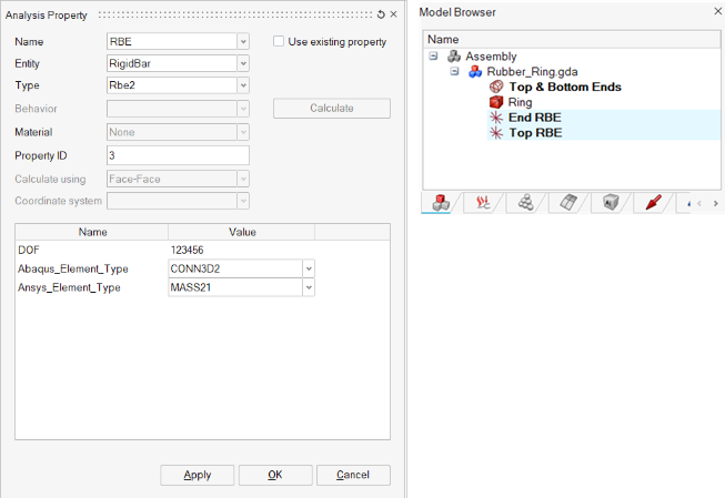
Figure 7. Assign Property to RBEs
Set Up Loads and Constraints
Create Contacts
Contacts are created between the Ring and End Faces to simulate the Compressing and Sliding action of the ring against the Top and Bottom Ends.
-
In the Define Contact dialog, set the parameters as shown
below.
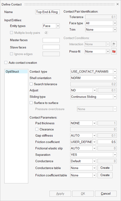
Figure 8. Contact Creation between Top End and Ring -
In the modeling window, select the Top End faces.
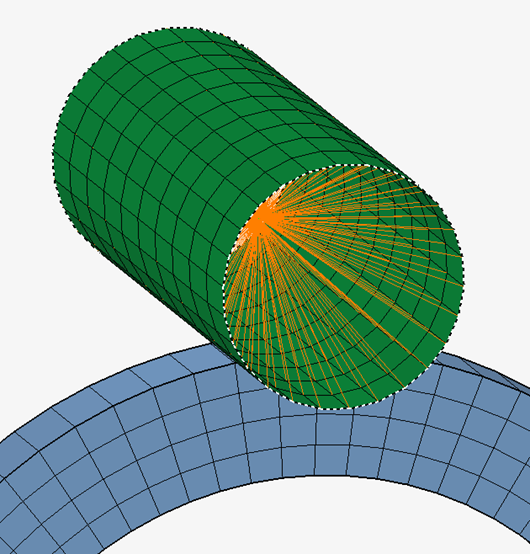
Figure 9. Main Face Inputs for Contact Creation -
In the modeling window, select the Outer Ring
faces.
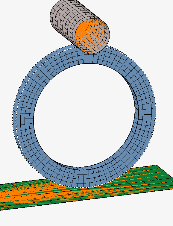
Figure 10. Secondary Face Inputs for Contact Creation -
Create a contact between Bottom End & Ring.
-
Set the following parameters in the Define Contact
dialog, as shown below.

Figure 11. Contact Creation between Bottom End and Ring -
In the modeling window, select the Bottom End
faces.
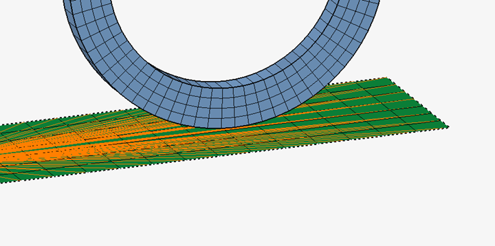
Figure 12. Main Face Inputs for Contact Creation -
In the modeling window, select the outer Ring
faces.
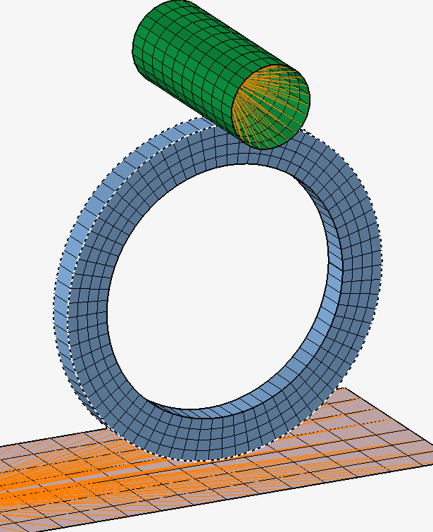
Figure 13. Secondary Face Inputs for Contact Creation
The created contact is listed in the Solution tab of the Model Browser. -
Set the following parameters in the Define Contact
dialog, as shown below.
-
Ceate a contact for the inner faces of the Ring.
-
Set the following parameters in the Define Contact
dialog, as shown below.
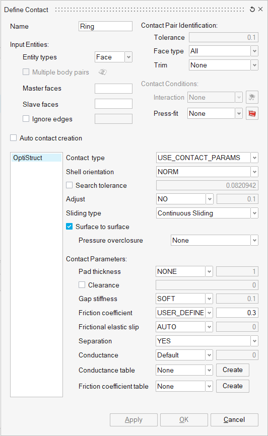
Figure 14. Contact Creation within Ring -
In the modeling window, select the top
semi-circular inner face of the ring.
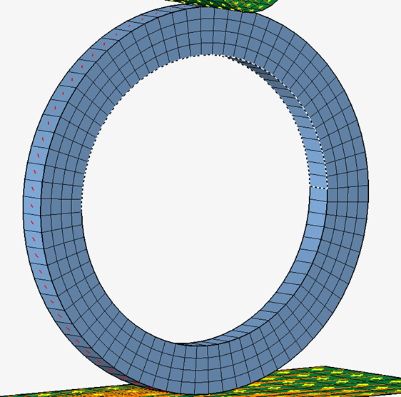
Figure 15. Top Semi-Circular Inner Face for Contact Creation -
In the modeling window, select the bottom
semi-circular inner face of the ring.
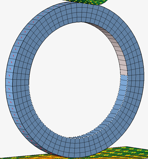
Figure 16. Bottom Semi-Circular Inner Face for Contact Creation
The contact will be created and added to the Solution tab in the Model Browser. -
Set the following parameters in the Define Contact
dialog, as shown below.
Create Loadcases
Define Constraints
-
Right-click in the modeling window and change the
selection filter to Face.
Figure 17. Face Selection Filter -
In the Fixed Constraint dialog, set the Axes as shown
below.
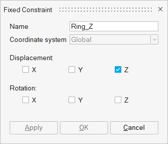
Figure 18. Constraint for the Ring Body Along Z Axis -
Right-click in the modeling window and change the
selection filter to Node.
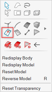
Figure 19. Node Selection Filter -
In the modeling window, select the Nodes on the front
and back sides of the Ring body, as shown below.
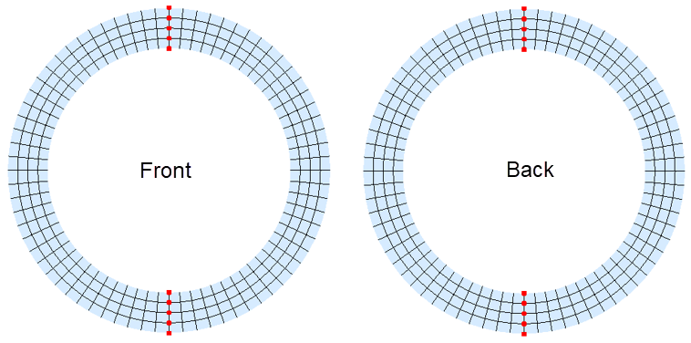
Figure 20. Node Selection for “Ring_X” Constraint -
In the Fixed Constraint dialog, set the Axes as shown
below and click Apply.
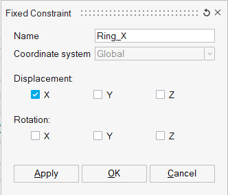
Figure 21. Constraint for the Ring Body Along X Axis -
Right-click in the modeling window and change the
selection filter to RBE Node.
Figure 22. RBE Node Selection Filter -
In the modeling window, select the RBE Main Node of the
End RBE, as shown below.
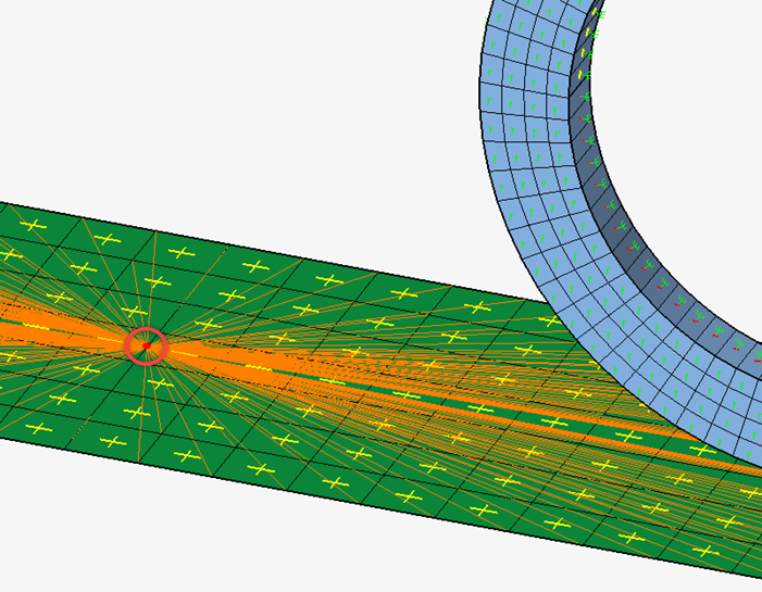
Figure 23. End RBE Main Node -
In the Fixed Constraint dialog, set the Axes as shown
below and click OK.
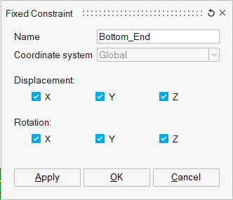
Figure 24. Constraint for the Bottom End Body
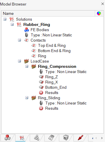
Figure 25. Constraints are added to the Ring_Compression LoadcaseA
Apply Enforced Displacement
-
Right-click in the modeling window and change the
selection filter to RBE Node.
Figure 26. RBE Node Selection Filter -
In the modeling window, select the RBE Main Node of the
Top RBE, as shown below.

Figure 27. Top RBE Main Node -
In the Enforced Constraint dialog, define the parameters
as shown below and click OK.
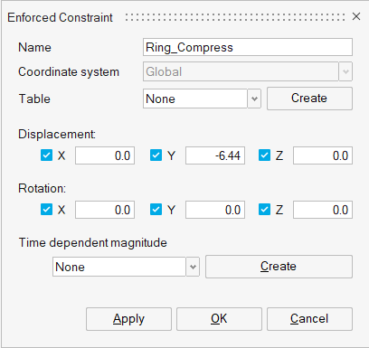
Figure 28. Enforced Displacement for Ring_CompressionThe Enforced Displacement is added to the Ring_Compression loadcase.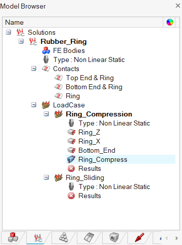
Figure 29. Enforced Displacement Added to Ring_Compression Loadcase -
Add constraints to the Ring_Sliding loadcase.
- In the Solutions tab of the Model Browser, right-click on the Ring_Sliding loadcase and select Set Current from the context menu.
- Right-click the Ring_Z constraint under Ring_Compression, and select Add to current Loadcase from the context menu.
- Right-click the Bottom_End constraint under Ring_Compression, and select Add to current Loadcase from the context menu.
The Ring_Z and Bottom_End constraints are added to the current Loadcase.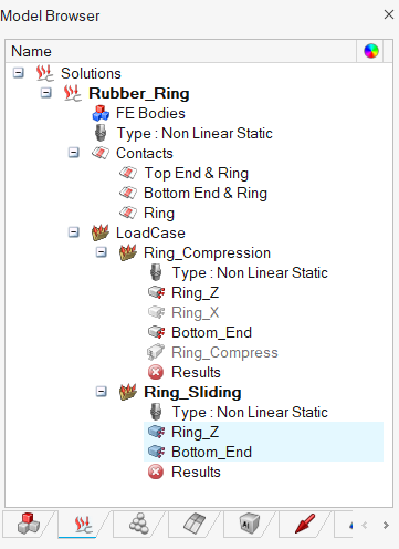
Figure 30. Ring_Z and Bottom_End Constraints Added to Ring_Sliding Loadcase -
In the Enforced Constraint dialog, define the parameters
as shown below.
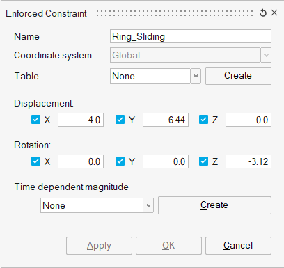
Figure 31. Enforced Displacement for Ring_Sliding -
In the modeling window, select the RBE Main Node of the
Top RBE, as shown below.
Figure 32. Top RBE Main Node -
In the Enforced Constraint dialog, click
OK.
The Enforced Displacement for generating the sliding force is added to the current loadcase.
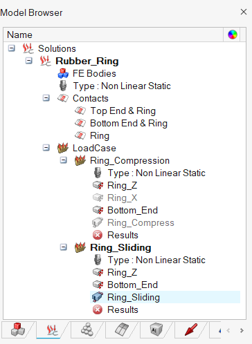
Figure 33. Enforced Displacement Added to Ring_Sliding Loadcase
Define Loadcase Parameters
-
In the Loadcase Parameters dialog, set the values as shown
below and click OK.
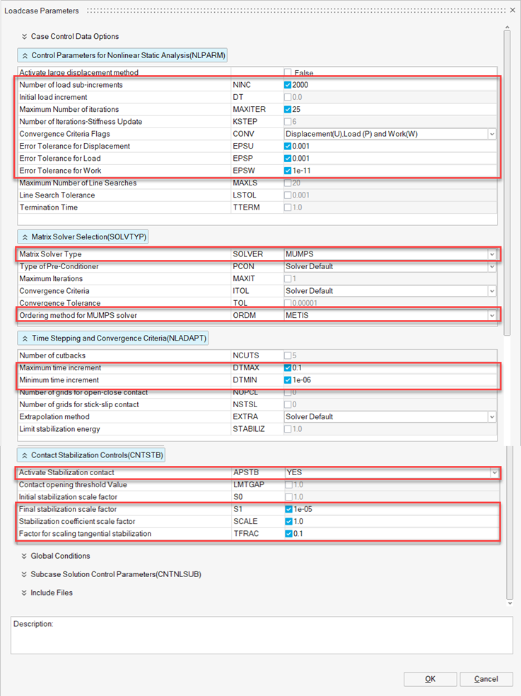
Figure 34. Set the Values for Loadcase Parameters for Ring_Compression Loadcase -
Create Loadcase parameters for the Ring_Sliding loadcase.
-
In the Loadcase Parameters dialog, set the values
as shown below and click OK.
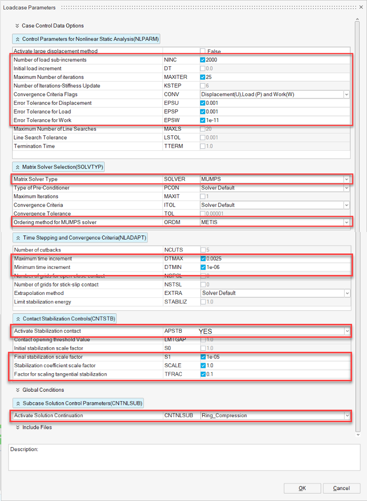
Figure 35. Create Loadcase Parameters for Ring_Sliding loadcase
-
In the Loadcase Parameters dialog, set the values
as shown below and click OK.
Create Solution Parameters and Output Requests
-
In the Solution Parameters dialog, set the values as shown
below and click OK.
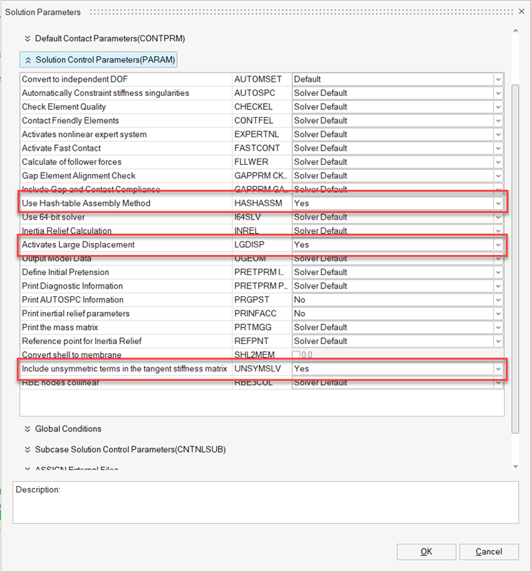
Figure 36. Set Values for Solution Parameters -
In the Result Request dialog, set the values as shown
below and click OK.
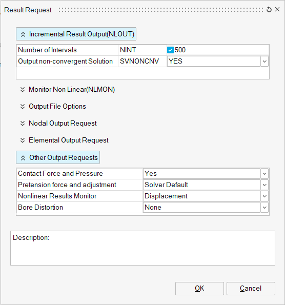
Figure 37. Set Values for Output Request
Solve and View Results
Solve the Solution
- Optional:
Change the Results components using the Results panel at the top of the
modeling window and animate the results using the
Animation panel at the bottom of the modeling window.
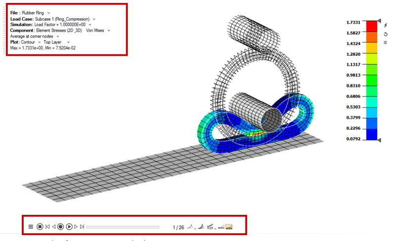
Figure 38. Results of Ring_Compression Loadcase