Run a topology optimization to maximize stiffness and explore the generated
shape.
In this lesson you will learn how to:
Create multiple load cases with unit loads in x, y, and z directions
Create forces and supports
Apply symmetry planes
Apply a single draw direction
Run a topology optimization to maximize stiffness
Explore generated shapes
Open the Y-bracket Model
Press F7 to open the Demo Browser.
Double-click the y-bracket.stmod file to load it in the
modeling window.
Make sure the display units in the Unit System Selector are set to
MKS (m kg N s).
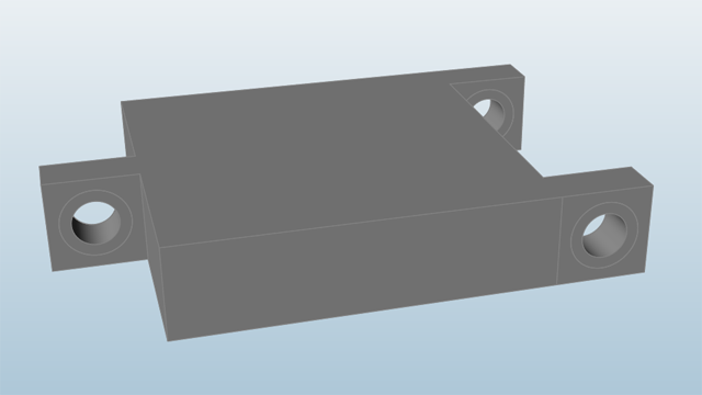
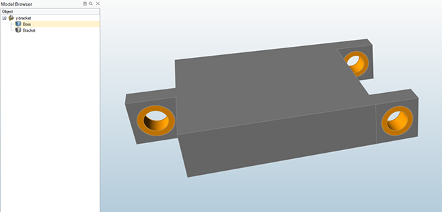
Use the right mouse button and the middle
mouse button to pan and rotate the view so the y-bracket is
positioned as shown below:
Define the Design Space
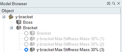
If not already visible, press F2 to open the Model
Browser.
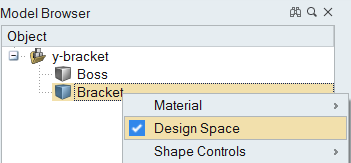
In the Model Browser, two parts are listed: Boss and Bracket. Click
Boss to select it.
The three cylindrical holes in the bracket turn yellow. While we will be
placing loads and supports on the boss materials, we do not want to subtract any
material from this part during optimization, so we do not want to include it in
the design space.
Right-click Bracket in the Model Browser and select
Design Space.
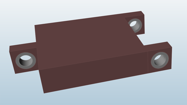
Click on an empty space in the modeling window. The red-brown color indicates
the area that material will be carved from during optimization.
Create a Center Hole Support and the First Load Case
Click the Structure tab on the ribbon.
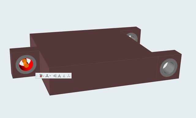
Select the Apply Supports tool on the Loads icon.
Click on the front boss material to apply the support.
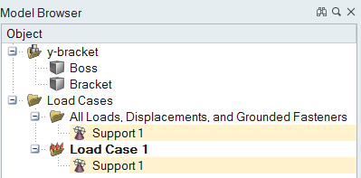
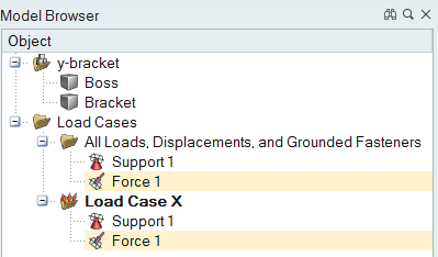
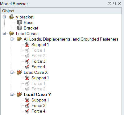
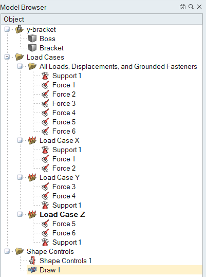
In the Model Browser, two new folders are created, one called Load Case
1 and the other called All Loads, Displacements, and Grounded Fasteners. Support
1 is added to both.
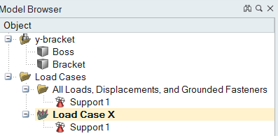
Click Load Case 1 twice to make it editable, rename it
Load Case X, and press
Enter.
The name of the load case is shown in bold, indicating that it is the
current load case. Any new loads or supports that you create will be added to it
automatically.
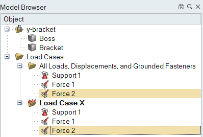
Apply Forces to Boss Materials
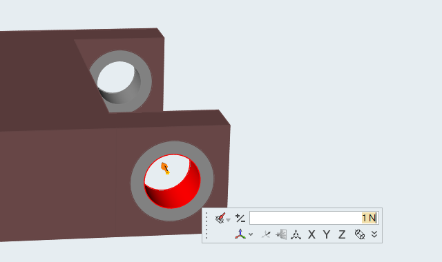
Select the Apply Force tool on the Loads icon.
Click on one of the rear boss materials to apply the force.
The force is initially applied in the negative x direction. Click the
+/- icon in the microdialog to reverse it to the
positive x direction.
Force 1 appears in the Model Browser in both the All Loads and Displacements
folder and Load Case X.
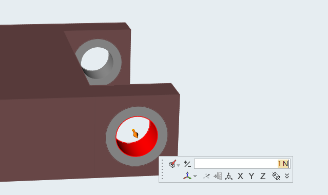
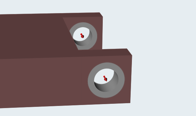
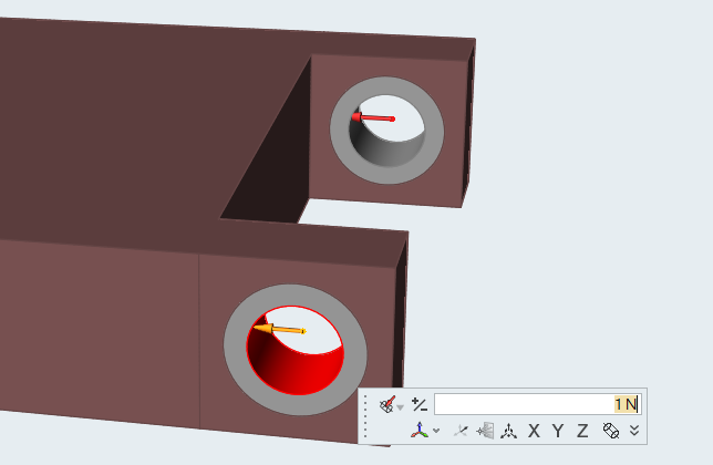
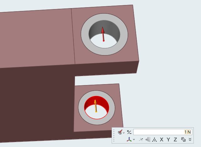
While the Apply Force tool is still active, click on the other rear boss
material and use the +/- icon to reverse the
direction.
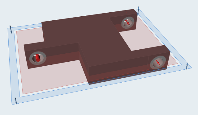
Both Force 1 and Force 2 should now be applied in the positive x
direction, as shown in the image below:
Force 2 appears in the Model Browser in both the All Loads and Displacements
folder and Load Case X.
Double right-click to exit the tool.
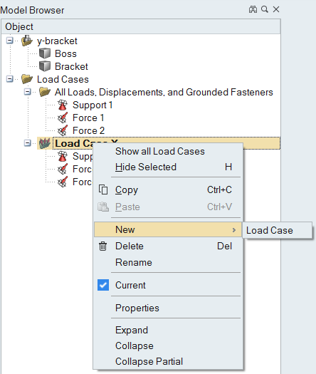
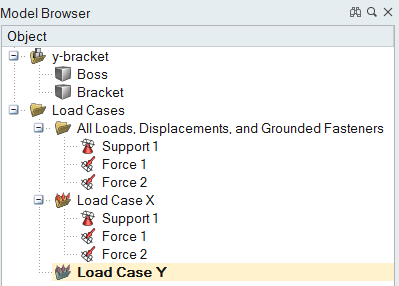
Create the Second Load Case
In the Model Browser, right-click on Load Case X and
select New > Load Case.
A new load case is added in the Model Browser.
Rename the load case Load Case Y and press
Enter.
This is now the current load case.
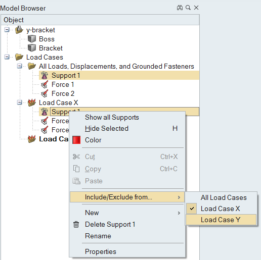
We want to use the same support from Load Case X in Load Case Y, so right-click
on Support 1 in the Model Browser and select
Include/Exclude from... >Load Case Y.
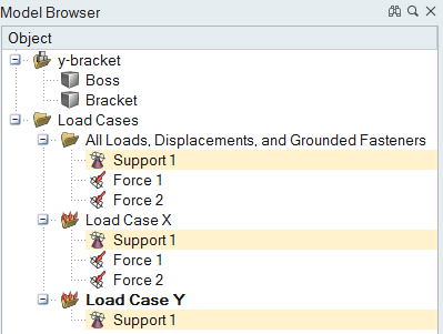
Support 1 is added to Load Case Y in the Model Browser.
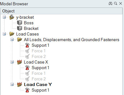
Click the icons next to Force 1 and Force 2 in the Model Browser to temporarily
hide these forces in the modeling window.
Select the Apply Force tool on the Loads icon.
Add two more forces, one to each of the rear boss materials in the negative y
direction.
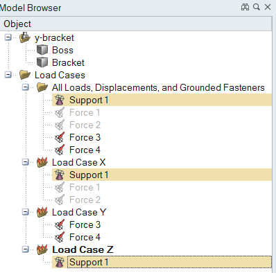
Force 3 and Force 4 have been added to Load Case Y in the Model Browser.
Double right-click to exit the tool.
Create the Third Load Case
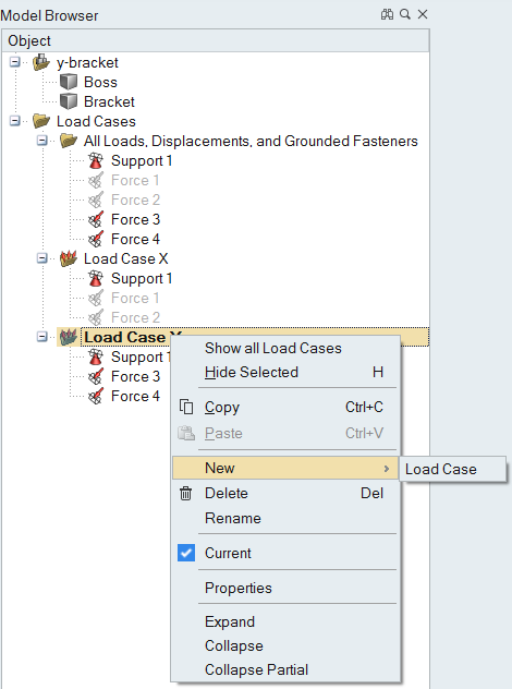
In the Model Browser, right-click on Load Case Y and
select New > Load Case.
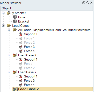
Rename the load case Load Case Z and press
Enter. This is now the current load case.
Click on Support 1 in the All Loads, Displacements, and
Grounded Fasteners folder in the Model Browser and drag it to Load Case Z.
Click the icons next to Force 3 and Force 4 in the Model Browser to temporarily
hide these forces in the modeling window.
Select the Apply Force tool on the Loads icon.
Add two more forces, one to each of the rear boss materials in the positive z
direction.
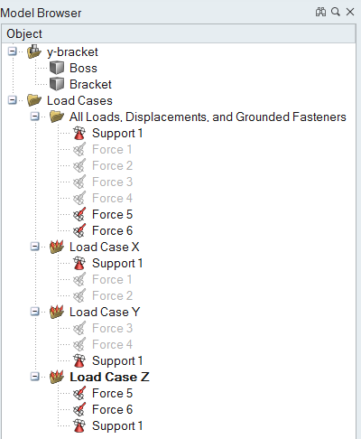
Check that Force 5 and Force 6 have been added to Load Case Z in the Model
Browser.
Double right-click to exit the tool.
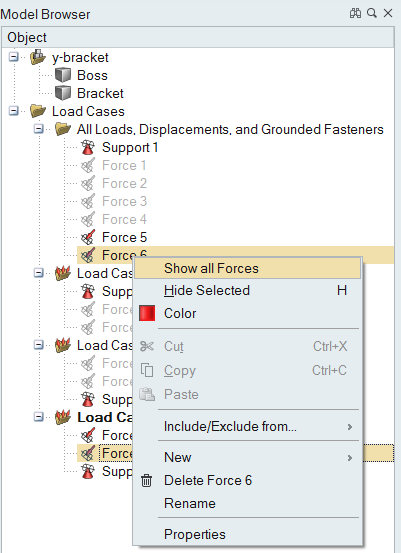
Right-click one of the forces in the Model Browser and select Show
all Forces in the context menu.
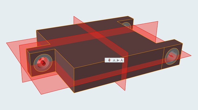
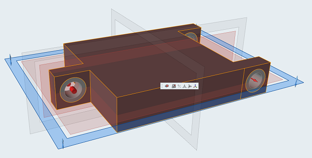
Add Symmetry Planes
Select the Symmetry tool on the Shape Controls
icon.
Select the Symmetric tool from the secondary
ribbon.
Click on the bracket in the modeling window to select it.
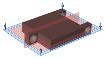
Three red symmetry planes appear.
Check that Shape Control 1 has been added to the Shape Controls folder in the
Model Browser.
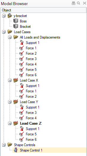
Click the plane shown below to deselect it.
The plane turns gray.
Double right-click to exit the tool.
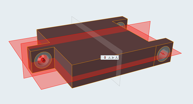
Add a Draw Direction
Select the Draw Direction tool on the Shape Controls
icon.
Select the Split Draw tool on the secondary
ribbon.
Click on the bracket in the modeling window to select it.
Three planes appear; the blue plane indicates the currently selected
parting plane.
Check that Draw 1 has been added to the Shape Controls folder in the Model
Browser.
Double right-click to exit the tool.
Run a Topology Optimization
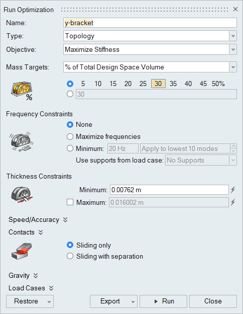
Click on the Optimize icon to open
the Run Optimization window.
Select Maximize Stiffness for the optimization
Objective.
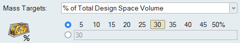
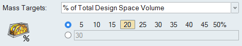
Under Mass targets, select % of Total Design Space
Volume from the drop-down menu and choose
30 percent.
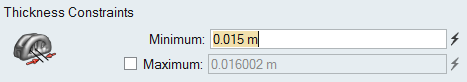
Under Thickness constraints, increase the Minimum to
0.015 m. (This will speed up the optimization.)
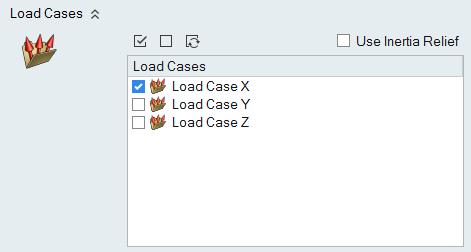
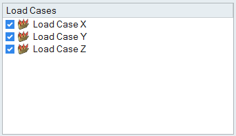
Under Load Cases, deselect Load Case Y and
Load Case Z.
This will run the optimization with only Load Case X applied.
Click Run.
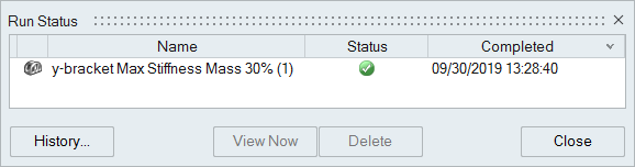
The Run Status window appears. A green check mark will appear when the
optimization is complete.
Double-click on the name of the run to view the results.
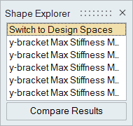
The optimized shape is displayed in the modeling window and is listed as
an alternative in the Shape Explorer.
Repeat the above procedure to run an optimization for Load Case Y.
Repeat the above procedure to run an optimization for Load Case Z.
The optimization runs for Load Case Y and Load Case Z appear as additional
alternatives in the Model Browser and the Shape Explorer.
Explore Optimized Shapes
Now run the optimization one more time using all three load cases
simultaneously. Click the Run Optimization icon to open the Run Optimization window, and
select all three load cases.
Change the Mass target to 20
percent of the total design space volume.
Click the Run.
When the optimization is complete, a green flag appears above the
Optimize icon group, indicating that the run completed successfully.
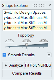
Click the green flag to view the optimized shape.
Drag the Topology slider in the Shape Explorer to
explore the optimized shape. Changing the topology adds and subtracts material,
giving you an idea of how this impacts the shape.
Note: Notice that as you drag the slider to the right, additional structures
emerge. This indicates that you need to rerun the optimization with a higher
percentage of material.
Click the Run Optimization icon to open the Run Optimization window.
Under Mass targets, change the % of Total Design Space
Volume to 30 percent.
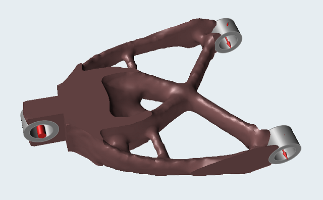
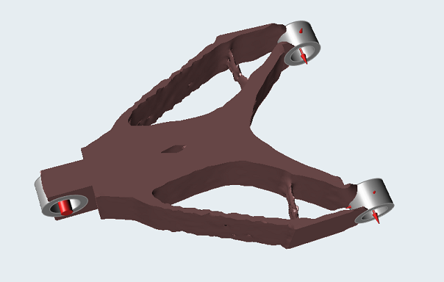
Click Run. When the optimization is complete, click the
green flag to view the optimized shape.
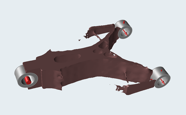
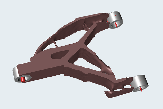
This should produce a result similar to the one below:
Change the Design Space and Rerun Optimization
Select Switch to Design Spaces in the Shape Explorer to
switch back to the original design space.
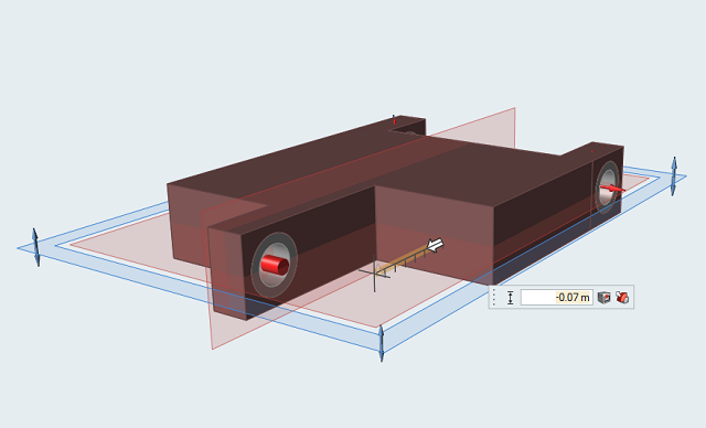
Select the Push/Pull Faces tool.
Reposition the model as shown below, then left-click on the right front face
and push it inward 0.07 m to make the design space
asymmetric.
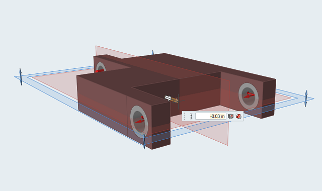
Rotate the model, then left-click on the rear face and push it inward
0.03 m.
Double right-click to exit the Push/Pull Faces tool.
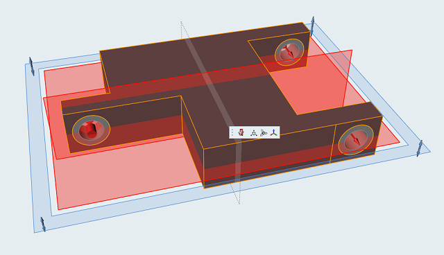
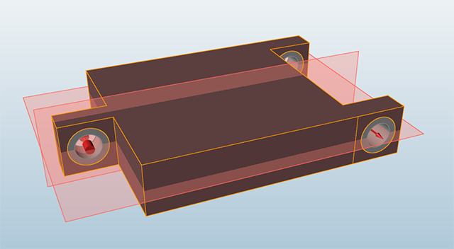
Reposition the model as shown, then double-click one of the red symmetry planes
to activate the Symmetric tool.
Click on the red plane in the z direction to deactivate it.
Double right-click to exit the tool.
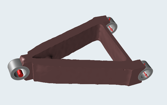
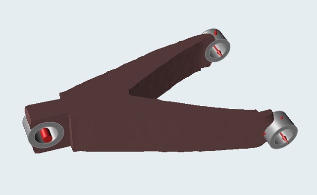
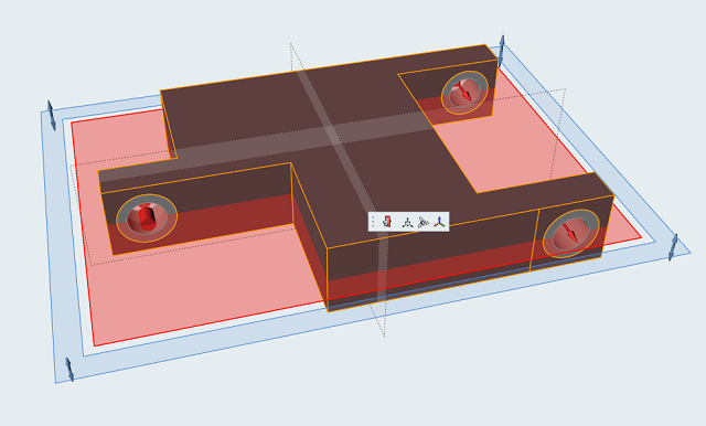
Rerun optimization with all three load cases active and a mass target with
% of Total Design Space Volume set to
30 percent.
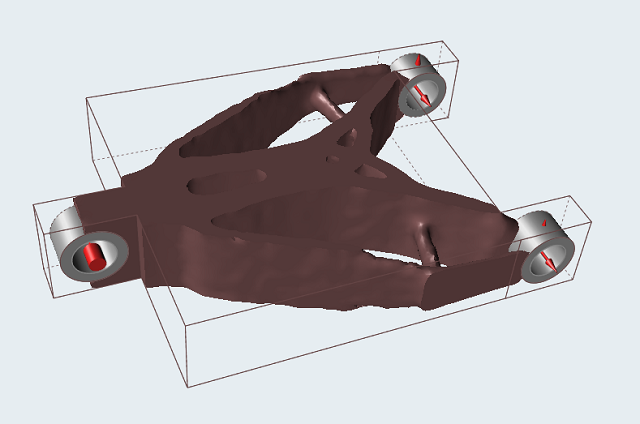
This should produce a result similar to the one below:
Adjust the Topology slider in the Shape Explorer to
explore the optimized shape.
To save and export the optimized shape, refer to the Saving and Exporting Files
tutorial.


 on the Optimize icon to open
the Run Optimization window.
on the Optimize icon to open
the Run Optimization window.