Apply an array of electric and magnetic dipoles in the model (in the form of a planar
aperture) that is equivalent to measured or calculated field values.
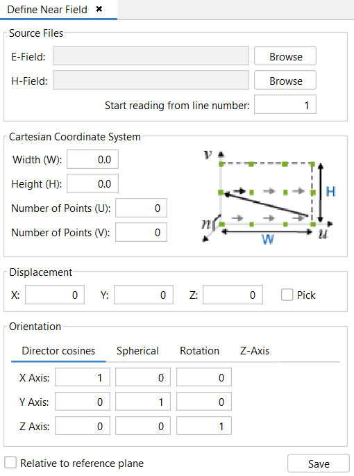
Source Files
The user can import the E-Field and H-Field files by pressing the
Browse button and selecting the text files in
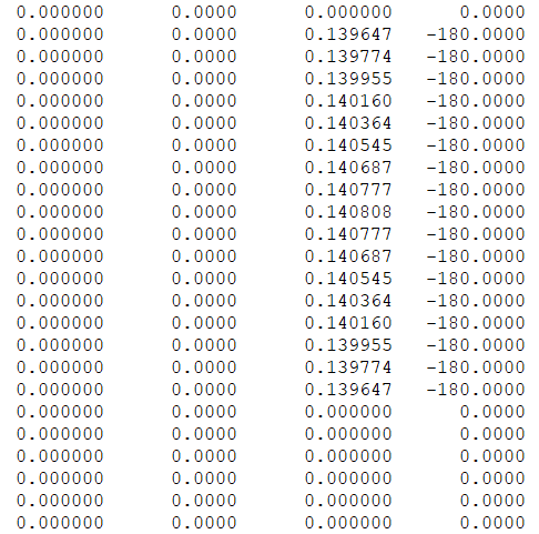
their hard drive. These files contain the electric and magnetic field
for every point in the U and V direction, four columns for the E-Field
file with EU (Amplitude V/m), EU (Phase deg),
EV (Amplitude V/m), EV (Phase deg); and four
columns for the H-Field file with HU (Amplitude V/m),
HU (Phase deg), HV (Amplitude V/m),
HV (Phase deg) (see Figure 2).
Figure 1. Define Near Field
Start reading from line number: Skip this
number of lines before reading the field values.
Figure 2. E-Field file example
Cartesian Coordinate System: Allows the
user to define the planar aperture, the E-Field and H-Field
files must contain a field value for each point defined in this
section.
Width (W): Array size in U
direction.
Height (H): Array size in V
direction.
Number of points (U): The number
of points in U direction.
Number of points (V): The number
of points in V direction.
Displacement: This parameter is a vector
that specifies the translation applied to the points when added
to the simulation.
Orientation: This parameter allows the
rotation applied to the points. There are several ways the user
can specify this rotation: by giving each of the axis directions
of the transformation, by specifying spherical rotation angles,
by specifying rotation angles on each axis or by specifying the
Z axis and a rotation angle.
If the Relative to reference plane check box is selected, the
displacement and rotation will be relative to the current reference plane coordinate
system.
When the user has finished setting up the parameters of the Near Field Source, they
need to press the Save button in order to add the antenna to
the simulation.