Test No. VNL08Find displacements of a hemispherical
shell loaded with inward and outward concentrated forces.
Definition
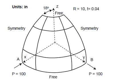
A hemispherical shell is loaded with inward and outward concentrated forces at point
A and point B, respectively. The hemisphere has an 18 degree hole at the top and the
quadrant of the hemisphere is modeled utilizing symmetric boundary conditions (Figure 1). Correspondingly, forces P shown in
Figure 1 are acting on the quadrant.
Displacement at points A and B are to be determined for force values P = 40, 60, and
100 lbf. Figure 1.
The material properties are:
Properties
Value
Modulus of Elasticity
6.825e+7 psi
Poisson's Ratio
0.3
Results
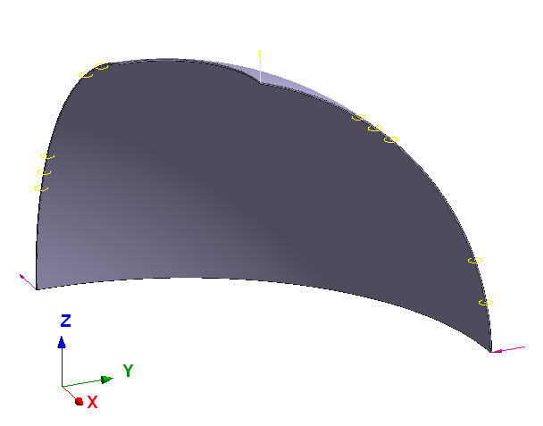
Symmetry conditions were simulated via sliding boundary
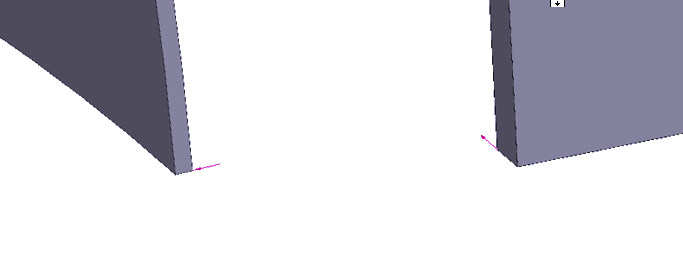
conditions applied at faces coinciding with symmetry planes (Figure 2). Concentrated forces were applied in
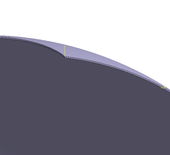
points of outer face of the sphere (Figure 3). In order to eliminate rigid body
motion along Z-axis a point on the top of the sphere was constrained in Z-direction
(Figure 4).
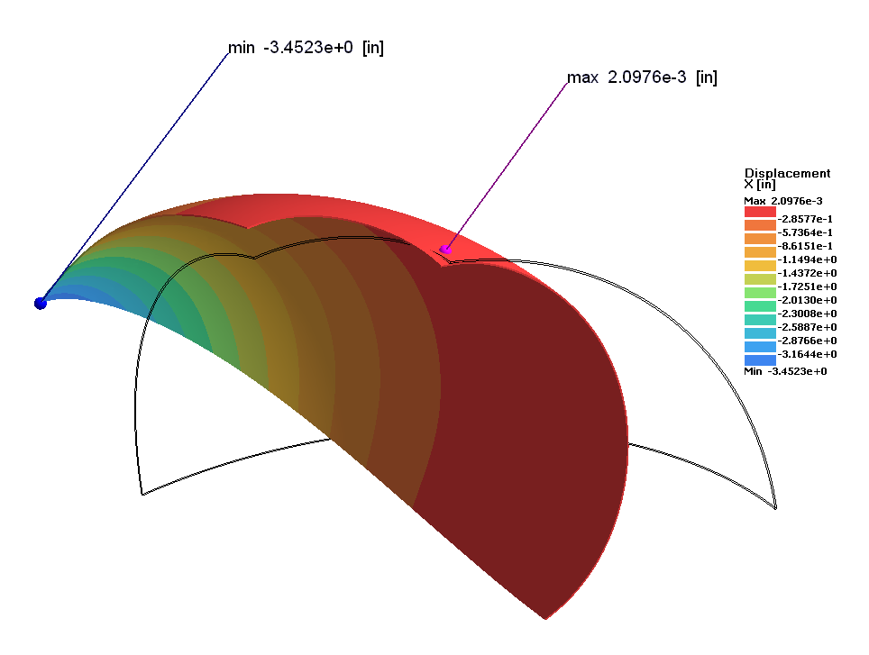
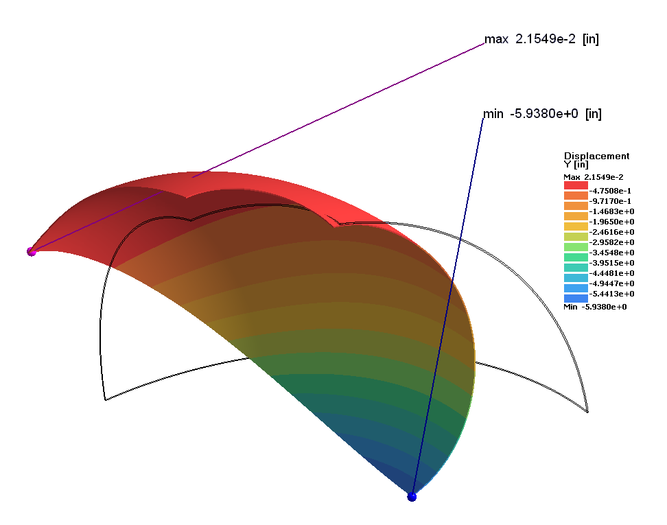
In Figure 5 and Figure 6 true deformations of the shell at load P = 100 lbf
are shown.
The following tables summarize the comparison results.
Load [lbf]
Ref Solution *, Uy at Point A
[in]
SimSolid, Displacement Ux at Point A
[in]
% Difference
40
-3.280
-3.148
-4.02%
60
-4.360
-4.120
-5.50
100
-5.950
-5.482
-7.87
Load [lbf]
Ref Solution *, Uy at Point B
[in]
SimSolid, Displacement Ux at Point B
[in]
% Difference
40
-2.330
-2.268
-2.66%
60
-2.830
-2.725
-3.71%
100
-3.430
-3.255
-5.10%
* Ref Solution is a thin shell model
Figure 2. Figure 3. Figure 4. Figure 5. Figure 6.
1 Test 3DNLG-9 from
NAFEMS Publication R0024 “A Review of Benchmark Problems for Geometric Non-linear
Behaviour of 3-D Beams and Shells (SUMMARY).”