This section explains the resolution best practice for passenger-type vehicles. The
recommendations are divided into:
General best practices
Hatchbacks/Compacts
Sedans/Coupes
SUVs/Vans
Pickup Trucks
Far field element size and used refinement levels
The simulation uses Refinement Levels (denoted RL), in which the cell size is halved
each time the RL increases. This increases the cell count in each direction by a
factor of two, and thus a factor 8 in 3d space. As each halved cell also doubles the
time-step count per same physical time, the total computational load for a section
by increasing the RL level is a factor 16. The far field element size (unit m)
defines the largest element size in the model and is set in the
.xml file or the inside the VWT. All additional mesh
controls are defined relative to the far field size.
With a recommended far field voxel size set to 0.192 meters (192 mm), the following
refinement levels will suffice for external aerodynamic simulations:
Refinement Level Voxel Size (mm):
RL 0: 192 mm
RL 1: 96 mm
RL 2: 48 mm
RL 3: 24 mm
RL 4: 12 mm
RL 5: 6 mm
RL 7: 1.5 mm
RL 8: 0.75 mm
Please note that RL6 (3mm) is the Refinement Level that will be used on the whole
vehicle for standard passenger vehicles, with local detailing sometimes at a higher
RL than that. Therefore, RL6 and RL7 are important reoccurring Refinement
Levels.
Types of refinement
Refinements in the simulation are defined in 3 different ways:
Refinement boxes
Custom refinement zones
Offset refinement zones
Overall offset
Offset per part
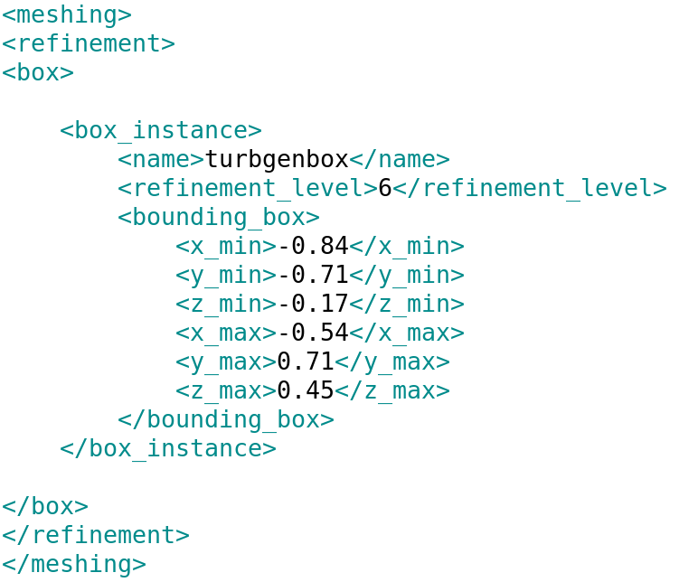
Refinement boxes are axes aligned and defined by minimum and maximum length in each
direction (x,y,z).
Custom zones are defined using a closed part in the .stl
geometry file, with resolution set inside that part. Please note that these custom
zones need to be present in the main .stl file that contains
the vehicle. Also note that if the custom zones are not defined but the part is
present in the .stl file, any custom zone part will be regarded
as having a solid wall. It is therefore important to check that all custom zones are
properly defined in the .xml deck or in VWT.
Offset zones are defined using an offset length and Resolution Level. Please note
that ultraFluidX will generate a minimum of 4 voxels
regardless of the offset length setting. If no part is assigned for an offset, it
will be applied to all solid surfaces. If a part is assigned, the offset will only
be applied to that particular surface. An offset instance can have multiple parts,
and a part can have multiple offsets overlaid on each other. The finest RL setting
will have precedence in that case, so if multiple layers are build up with
decreasing RL, the coarser ones will need to be defined with an additional offset
length of all underlying higher RLs. For example if one wants 4 layers of 1.5mm RL7
and 12 layers of 3mm RL6 on top, the offset lengths would be 4*1.5=6mm for RL7 and
6mm+12*3mm=42mm for RL6.
In the sections below, these 3 types of Refinement will be used to capture relevant
physics around the vehicle.
Vehicle refinement for outer regions (RL 1 through 3)
This sections goes through the resolution setup in steps, working inward from the
outermost resolution.
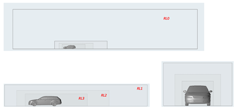
The outer 3 refinement regions around the vehicle are boxes, with a shift towards the
rear of the tunnel to capture the wake structures. Figure 1. Outer domain RL0 and the first 3 RLs indicated on the DrivAer Estate
model
It is recommended that RL1 is at least:
X: 3 car lengths downstream, 1 car length upstream of the vehicle
Y: at least one vehicle width off to the sides
Z: at least one vehicle height above the vehicle
RL2 and RL3 are scaled down from there. It is recommended that RL3 end one car length
behind the vehicle.
Refinement zones closer to the vehicle (RL4 and
RL5)
Near the vehicle further, RL4 and RL5 are defined to capture:
the underbody flow
the wake
the wheels
the upstream boundary layer (in case of a VWT floor with a defined BL
suction location)
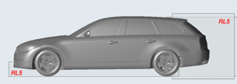
The figure below indicates the location of refinement for the underbody flow and
wake. Figure 2. First two zones of interest to capture using RL5
It is possible to apply resolution in these regions using either box or
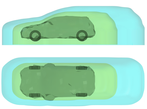
custom refinement zones. Recommended practice is to create custom refinement zones
using loose wraps of the car that are scaled and repeated with a shifting towards
the downstream side to encapsulate the wake. Figure 3. RL4 (blue) and RL5 (green) custom zones based on scaled wraps around a
vehicle
Note: Creation of scaled and translated custom zones can be achieved in HyperMesh. In short: Wrap the entire body & wheels
with a 12.0 mm loose wrap, scale 105%, copy it multiple times till 1.5m aft (for
the wake), and a few times down (for the underbody). Then, wrap all these copies
with a 12.0 mm convex wrap. Import this wrap and assign as resolution level of 5
(RL5).
For very 'boxy' cars, or when voxel count is less critical, it is possible to set
box refinement zones for RL5 and RL4. In that case follow the above figure for RL5, and
add an extra RL4 box enclosing the entire vehicle, stretching 1 car length behind. The
width of the RL5 sections should be about 15% wider than the vehicle.
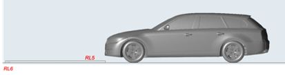
VWT floor refinements
In the case of wind tunnel modeling, optional belts and a boundary layer suction
location are present. In order to adequately capture the flow development in those
regions, resolution needs to be placed correctly.
For the boundary layer suction location, not only the region itself needs to be
resolved, but also the development of the tunnel floor boundary layer past this
element. It is recommended to put one RL6 box around the suction location, spanning
two vehicle widths and extending 8 voxels (24mm) upstream, downstream, and in
height. Then, to grow the boundary layer, create an RL5 box that runs into the
vehicle RL5 zone, extending two vehicle widths, 6 voxels (36mm) in height. Figure 4. Resolution placement for the boundary layer suction device
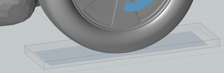
In the case of wheel belts, extra refinement zones just around the belts are
recommended, RL6 4 voxels (12mm) high, spanning past the extents of these belts.
Please note that this is not needed for main center belts or T-belts, as the focus
is solely to capture the squeezed flow in front of the tire patch. Refinement boxes
at the tire/road interface are also recommended in the absence of belts (open road
simulation). In that case, place resolution starting around 100mm in front of the
tire/floor contact location and for 100mm downstream as well, 50mm beyond the tire
extent on the sides. Figure 5. Refinement RL6 boxes around wheel belts
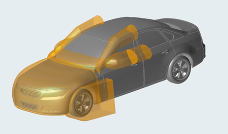
Custom refinements
In order to capture complex regions of high shear and separated flow, specific custom
refinements are recommended around parts of the vehicle.
The recommended zones include (but not limited to):
Nose of vehicle
Air dams/spoilers
Cowls
A-pillar vortices
Mirror wakes
Wheels
Figure 6. Example of custom refinement zones around the vehicle for capturing flow
details
In the sections below, each custom refinement zone will be explained in detail.
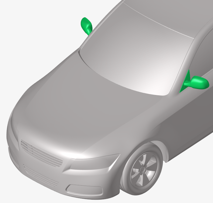
Mirror custom refinement
The mirror needs special attention and two refinement zones need to be
created. First, start by wrapping the mirror with a 12 mm convex wrap.
Move the wrap rearward 100 mm and wrap the two wraps with a 12 mm convex
wrap then scale this wrap by 105%. This will be a refinement zone of
level RL6. Repeat the process by scaling the first mirror wrap by 120%
and copying the wrap rearward 1.0 m and wrapping them with a 12 mm
convex wrap. This wrap will become a resolution zone of RL5.
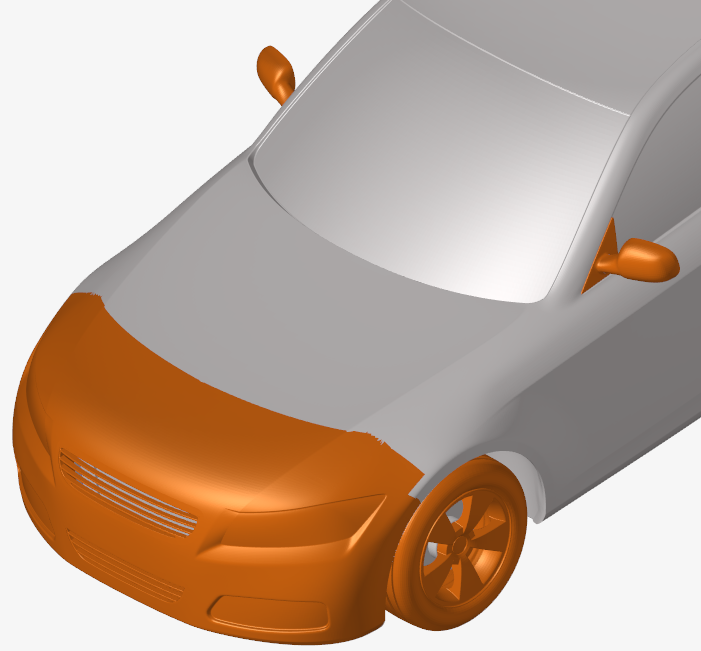
Nose custom refinement
Select the nose region and add surfaces in order to close the region.
Loose wrap around the region, scaling and extruding down to the floor.
This covers the engine bay and some wakes. It is recommended to set to
RL5 (6mm) to capture the engine bay and the surrounding flow.
Cowl and A-pillar custom region
Create a simplified shape that generously covers any cowl vortex and
separation/reattachment on the windscreen. RL6 is recommended.
Offset refinements
Now that separated flow regions are covered using custom zones and/or boxes, offsets
regions are used to capture the boundary layer flow in regions of interest.
As mentioned, offset regions can be general on all parts (when no specific part is
indicated) or on separate sections. The offsets are used to set resolution in the
boundary layers on the vehicle in order to capture the necessary physics. As
boundary layers are growing over the vehicle, you see more placement of resolution
on the upwind parts of the vehicle, where boundary layers are typically thinner.
Also, separations and the effects of pressure gradients are important. Therefore,
one will also see placement of resolution on parts that (possibly) separate, and
rounded corners where large pressure gradients occur.
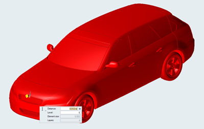
General offset refinement on whole body
As a starting point, for the general offset, 4 voxels (4x3mm=12mm) of
RL6 is recommended on the whole vehicle. Please note that in case of
scaling the far-field resolution, the offset distance needs to be scaled
to match 4 voxels again. This is true for both general and part
offsets. Figure 7. Whole body offset on all parts: RL6 4 voxels
Specific part offsets
Next, specific part offsets need to be defined. The following regions
are recommended for extra offset refinement:
Area around front bumper and nose (thin developing boundary
layers)
A-pillar and roof line (accelerated flow, separation
capturing)
Under the nose and around front wheels: air-dams, spoilers,
splitter areas, deflectors
Back/tail end of vehicle: C/D pillars, side of bumper, roof
spoilers, and so on
Tires
Mirrors
Any other elements that are being specifically investigated
All these areas are recommended to have: 4 voxels in RL7
(4*1.5mm=4mm) plus 12 voxels offset of RL6 over that (+12x3mm=+36mm
for a total of 40mm RL6 offset)
On the last point, it is recommended to place additional resolution
when investigating the effect of a specific part, for example a
spoiler or lip.
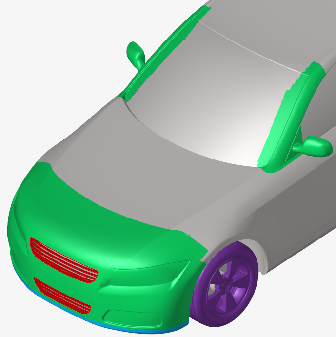
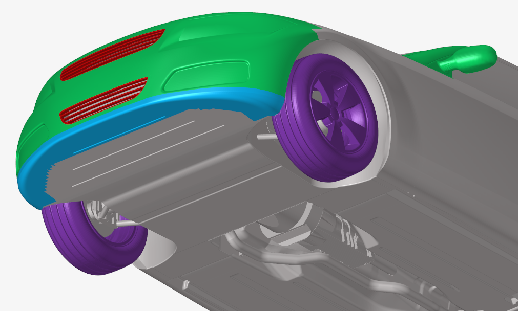
The figure below shows some typical resolution placement for the
front of the vehicle. The mirrors have thin boundary layers, changes
in pressure gradients and separations, and are therefore part of the
increased resolution sections. Next, the A-pillars are set to
increased resolution, as formation of an A-pillar vortex is prone
here. Note that the resolution definition stretches beyond the
actual A-pillar part in both the upstream and downstream direction.
It is recommended to isolate and include these sections to have the
resolution interface further from where the relevant physics occur.
The nose of the vehicle is also covered, as there is a thin
developing boundary layer all around, as well as pressure gradients.
The tires are also set to a higher resolution, in part due to their
curvature into the flow. The tire parts in purple should have a
minimum of RL7 offset. Using RL8 on the tires will improve the
solution, but this significantly increase simulation time. Note that
the lower bumper edge is indicated in a separate color. If the lower
bumper has a sharp edge, separation may occur. It is recommend to
further extend the RL7 offset on this part to capture the separated
flow. The grill (in red) also needs attention, and is covered
separately below. Figure 8. Example regions for partial offsets Figure 9. Lower bumper/air dam area offsets
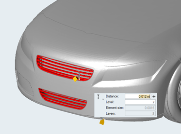
Depending on the geometry, grills could need an offset of RL7 (1.5mm)
or even RL8 (0.75mm) on grill elements to ensure enough voxels fit
through the gaps. A bare minimum voxel count of 4 voxels is needed
across a gap, with a recommended minimum of 6. Please note that this
can be achieved using a simple offset on an isolated grill part. Figure 10. Possible grill offsets
The separation location on the back end of the vehicles is important
for capturing the right flow physics. It is recommended that the
areas around the tail of the vehicle have an RL7 offset of 4 layers.
The specific shape and location of these offset regions might differ
by vehicle type. Specific vehicle types are elaborated below.
Wheels and tires
Parts that rotate are identified as wheels. There are two methods currently available
to describe rotation in ultraFluidX. They are:
Rotating walls
Moving Reference Frame (MRF)
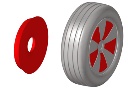
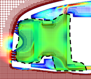
For simulation of the flow between the rim spokes of passenger vehicles, a Moving
Reference Frame (MRF) approach is recommended. The MRF can be created by applying
rotational symmetry around a spoke. This creates a snug closure between the spokes.
The MRF is allowed to intersect the spokes; individual pocket surfaces are thus not
needed. Figure 11. MRF zone created and its position with respect to the wheel
spokes
Special preparations for fully treaded, deformed tires
Standard best practice is to use non-treaded tires that are undeformed, and intersect
with the ground plane, with longitudinal stripes (axisymmetric) remaining in the
part.
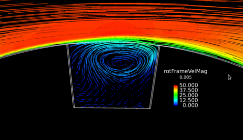
Scanned detailed threaded tires can be implemented using the rotating wall condition.
In case of features that are not fully parallel to the rotation direction, the
rotating wall condition allows for a crude model of cavity flow: partly
perpendicular will have an inflow/outflow component using this boundary condition.
This prevents artificial separations around the tire sidewall. Figure 12. Example cavity flow when transformed in a rotating coordinate
frame
For more detailed cavity flows (like in for example wheel/tire studies), an MRF
filling the tread cavities can be used. The MRF zone can be created using rotational
symmetry, as long as the MRF surface does not stick through the tire surfaces next
to the cavities. Please note that this usage is not recommended in the general Best
Practice for vehicles, only for special detailed studies on tires. If interested,
please contact us regarding detailed setup of scanned and/or deformed tires. Figure 13. Optional MRF (light blue) in tire treads, not needed in base Best
Practice
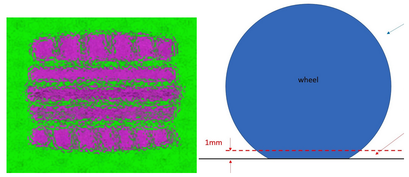
If you use scanned deformed tires that are flattened at the ground intersect, there
is experience in setting up the detailed ground/tire boundary. For example, specific
patches are created using a cut-plane 1mm above the ground, and grouping any
elements that are inside this intersect into a separate part. Please note again that
this usage is not recommended in the general Best Practice for vehicles, only for
special detailed studies on tires. Figure 14. Deformed tire interface patch for special tire studies
Porous media and cooling flow
Porous media are defined using an inflow plane, outflow plane, and sides. See the
chapter on VWT for the setup details there. To capture the correct cooling flow
physics, a box resolution region is recommended that is loose around the porous
media zone. This zone captures the flow from grills as well as the outflow along the
front of the engine block past the porous media. RL5 is a recommended setting for
this. Figure 15. Cooling flow region in RL5, shown on DrivAer model
A minimum number of 6 voxels is recommended across the thickness of any porous media,
where possible. Therefore, the cooling pack itself would often receive a box
refinement of RL6 tight around the pack.
Strategy for Large-Eddy Simulations
Introduction
ultraFluidX employs physics based modeling
using a two-way coupled system, where the shear stress of the wall model
projected onto the surface is continuously being matched with a shear
force in the bulk flow. This provides a more accurate model versus
one-way coupling, where the shear forces are based on modeled
parameters. For thin boundary layers, where the resolution is too large
to capture the small vortices, there are two techniques used to more
accurately model the appropriate physics. These are as follows:
Wall model variants per part
Vortex generator to initiate turbulent eddies
Background for usage
ultraFluidX is a Large-Eddy Simulation solver
that provides details of the flow, including the flow in the boundary
layers. Changes to the two-way coupled model are needed where thin upstream
boundary layers occur on curved regions, and the resolution in terms of
voxels over boundary layer thickness is low. Typical regions on automotive
vehicles are listed in order of importance:
Mirrors
Nose and front bumper
Leading edges of tires
Figure 16.
For reach region a modeling strategy is employed to capture the
appropriate physics.
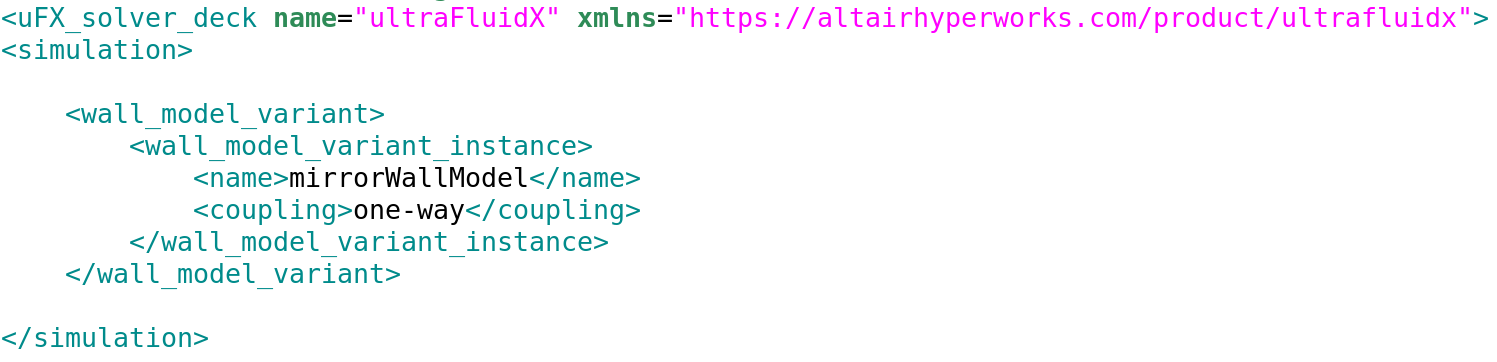
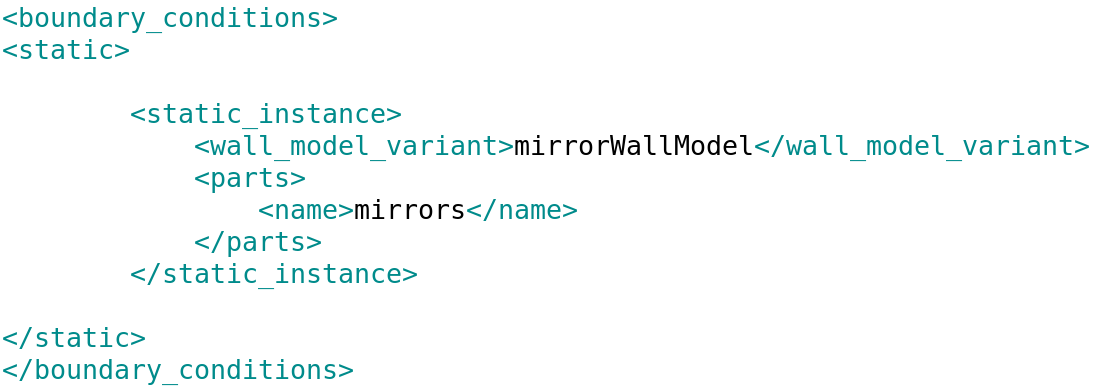
Wall Model Variants
Application: Mirrors
The mirrors typically have a high curvature and thin boundary layers
before separating over the cover edge. To model the correct physics on
the mirror, a wall model variant is specified on the mirror part. The
wall model variant on the mirrors uses the one-way coupled model instead
of the default two-way coupled model. The one-way coupled model is more
robust in predicting the flow and drag when there is not enough
resolution and length to develop the boundary layer fluctuations. Figure 17.
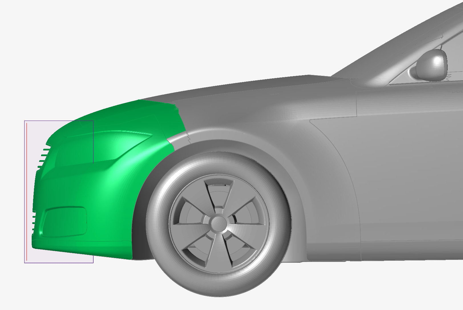
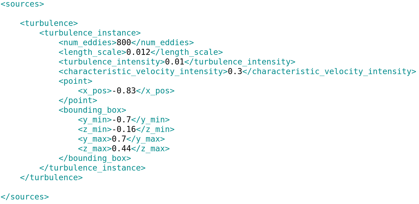
The nose and bumper of an automotive vehicle includes a stagnation area
and a developing boundary layers around the curvature of the bumper and
nose. This area creates the upstream conditions for the rest of the
vehicle. In order to aid the development of the boundary layer, the
usage of a turbulence generator is recommended. The turbulence generator
needs to be close to the stagnation region to create turbulence in the
thin boundary layers in the form of randomized vortices. A box
resolution zone of RL6 is set around the turbulence generator that
covers approximately 10mm upstream of the generator and 300mm downstream
to cover the bumper curvature.
The turbulence generator can be placed
based on the external dimensions of the vehicle:
x direction: 24mm upstream from the xmin location
y direction: + and -80% of the width/2 in y direction (as
defined from the symmetry line)
z direction: 10% to 60% of the height in z (as defined from
the ground)
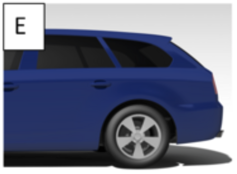
Hatchbacks, compacts, estates, and the like often have a geometrically defined
separation line (at least for the roof section). This simplifies the separation
modeling; however, some care needs to be given on these sections as well. Often
there is a round-off and/or a spoiler element. Below an example estate-back on the
TUMunich DrivAer model. Figure 23. Estate (E) models are examples of mentioned geometry types in this
section source: https://www.mw.tum.de/en/aer/research-groups/automotive/drivaer/
It is recommended best practice to place RL7 on locations where separation is bound
to occur. For spoilers, create an offset for the whole element. For round-offs,
include 10-30cm upstream and 5-15cm downstream of the expected separation into the
RL7 region. The sides and rear bumpers can still have geometrically undefined
separation lines; it is, therefore recommended to also place sufficient RL7 on the
sides in these regions for all the surface area where separation of significant
thickening of the boundary layer under adverse pressure can occur. The figure below
illustrates the strategy: Figure 24. RL7 regions on the tail end of hatchbacks, compacts, or estates. Resolution is placed in zones where separation is bound to happen, all
around the base. Note the special consideration for any spoiler element (in
blue).
Note that the base does not need to be in RL7, which saves elements. Also, the RL7
region extends past the separation edge as mentioned before. The shape of the RL7
region might not span a single part, but can wrap sections of adjacent parts, as
well. In the figure above for example, part of the rear glass is included in the
region. Often taillights are in this zone. It is recommended to place the whole
taillight unit in the RL7 region.
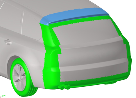
Considerations for Sedans/Coupes/Fastbacks
Sedans, coupes, fastbacks and the like often have a sweeping roof line where the
boundary layer thickening under adverse pressure gradient. Also separations and
reattachments can occur. Below examples of a sedan and coupe model of the TUMunich
DrivAer. Figure 25. Fastback (F) and Notchback (N) models are examples of mentioned geometry
types in this sectionsource: https://www.mw.tum.de/en/aer/research-groups/automotive/drivaer/
Separation lines (if any) on curved surfaces facing the rear are harder to predict
than on geometrically sharp edges. As such, best practice is to apply RL7 on the
rear window/trunk sections, as well as on any side surfaces where separations can
occur. The RL7 regions can be divided into sections with known separations (depicted
in green below) and sections where the boundary layer experiences an adverse
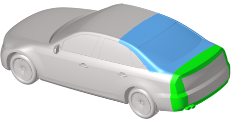
pressure gradient and is prone to possible separation (depicted in blue below). Figure 26. RL7 regions for consideration, known separation edges (green), adverse
thickening boundary layers (blue). For cleanliness of the image, the other high resolution regions on the
vehicle are not indicated (including rear tires).
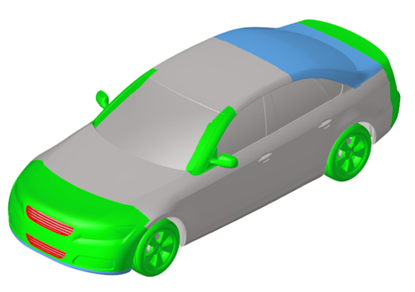
A final image highlighting the geometric details with RL7 recommendations is shown
below. Note the grill (in red) may need additional refinement. Figure 27. Complete offset strategy for the DrivAer sedan model
Considerations for SUVs/Pickup Trucks/Vans
Refinement zones
Due to the increased sizes typically of SUVs/pickups/vans, the far-field
resolution might need to be increased to have a reasonable cell count
for the simulation. RL6 is 3mm on passenger cars, 3.2mm or 3.5mm RL6 is
recommended depending on the size. For a 3.2mm setup for example, the
resolution regions would look like this:
Refinement Level Voxel Size (mm):
RL 0: 204.8 mm
RL 1: 102.4 mm
RL 2: 51.2 mm
RL 3: 25.6 mm
RL 5: 6.4 mm
RL 6: 3.2 mm
RL 7: 1.6 mm
RL 8: 0.8 mm
All defined offset regions need to be scaled accordingly to keep a
similar voxel count. VWT has an entry for setting the number of voxels
in a certain offset region; this can be used for scaling.
Custom refinement cowl/A-pillar/mirrors
When windscreens are more upright, a separation can occur upstream on
the hood. Make sure that the cowl custom refinement region is enlarged
to capture this phenomenon. A-pillar vortices and mirror wakes can be
larger, enlarge the refinement regions and blend with overlap with the
cowl and mirror wake regions.
Truck beds
Truck beds can have complex flows in them, where the flow from the cab
interacts with the tailgate. It is recommended to add a region of RL5
surrounding the whole truck bed. Both the cab end, top of the tailgate
area and sides of the truck around the taillights should have RL7
refinements as defined before (4x RL7 + 12x RL6), as the separation. The
shear layer at the end of the cab should be captured in an RL6 custom
refinement region for about 30cm, as well as the volume around the top
of the tailgate.
In conclusion: General Mesh Setup for Passenger Cars
Based on the described best practice, a vehicle of 100-250 million voxels is created,
depending on the vehicle details. A typical runtime of around 8 hours on Nvidia 8x
V100 GPUs is estimated for 4 seconds of physical time using this scheme.