Frame
1. Type of frame
The tools available in the housing tab allow defining the frame topology.
Three choices are available to define this topology: None, Circular or Square.
By default, housing type is set to “None”. There is no frame.
Important note: When “None” is selected, accesses to External cooling and Internal cooling environments are locked.
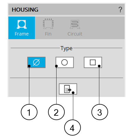 |
1 | Default setting : Housing type is « None » The machine has no frame. |
| 2 | Button to select a Circular shape frame. | |
| 3 | Button to select a Square shape frame. | |
| 4 | Icon to export frame data into *.txt or *.xlsx files. | |
| Frame type available | ||
 |
|
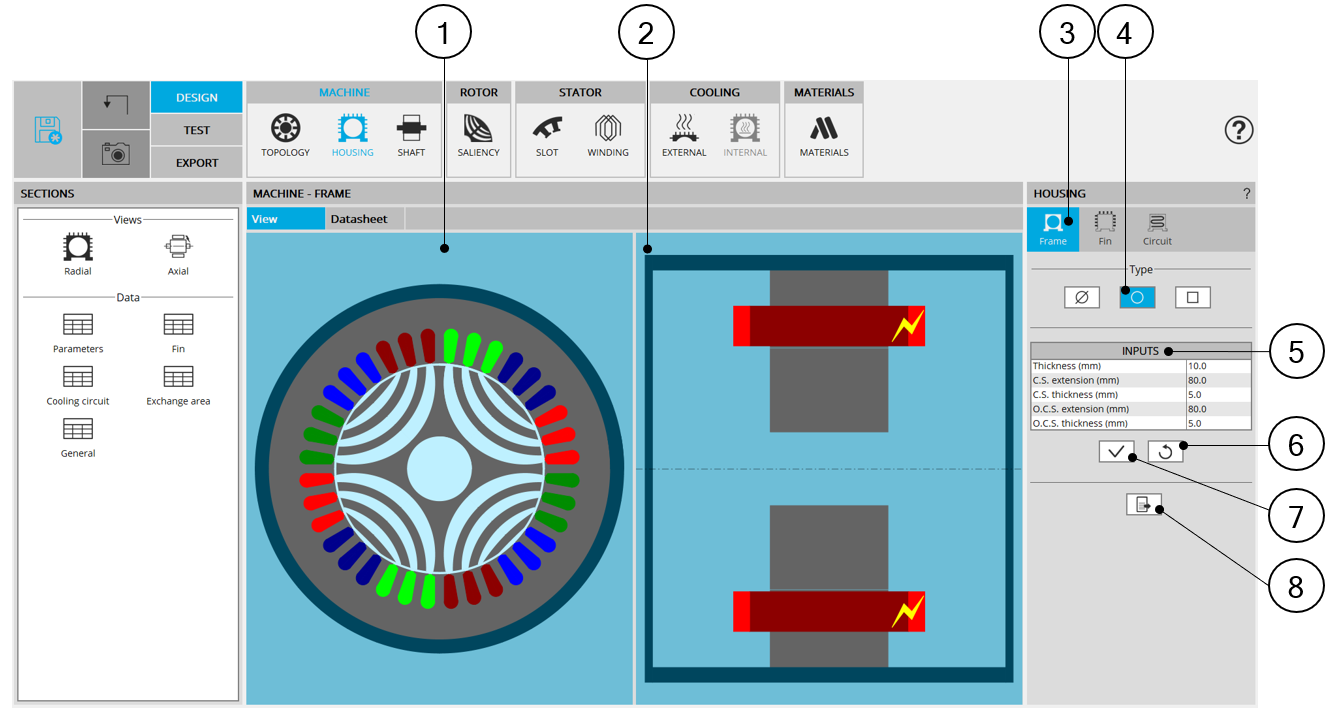
| Circular shape frame design area | |
| 1 | Radial view of the motor, including the housing topology and dimensions. |
| 2 | Axial view of the motor, including the housing topology and dimensions. |
| 3 | The section frame is selected to define the type and dimensions of the frame. |
| 4 | Selected button to set a circular shape frame. |
| 5 | User input parameters to define the frame dimensions. For more information see below. |
| 6 | Button to restore default input values. |
| 7 | Button to apply inputs. Pressing the enter key twice applies inputs too. |
| 8 | Icon to export frame data into *.txt or *.xlsx files. |
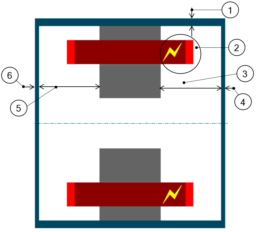 |
1 | Thickness of the frame. Allowed range of values ]0, 50] mm. |
| 2 | Connection side (C.S.) is identified by yellow lightning. | |
| 3 | Connection side extension. Allowed range of values [0, 20000] mm. | |
| 4 | Connection side – End-plate thickness. Allowed range of values [0, 50] mm. | |
| 5 | Opposite connection side extension. Allowed range of values [0, 20000] mm. | |
| 6 | Opposite connection side – End-plate thickness. Allowed range of values [0, 50] mm. | |
| User input parameters to define frame dimensions in the axial view | ||
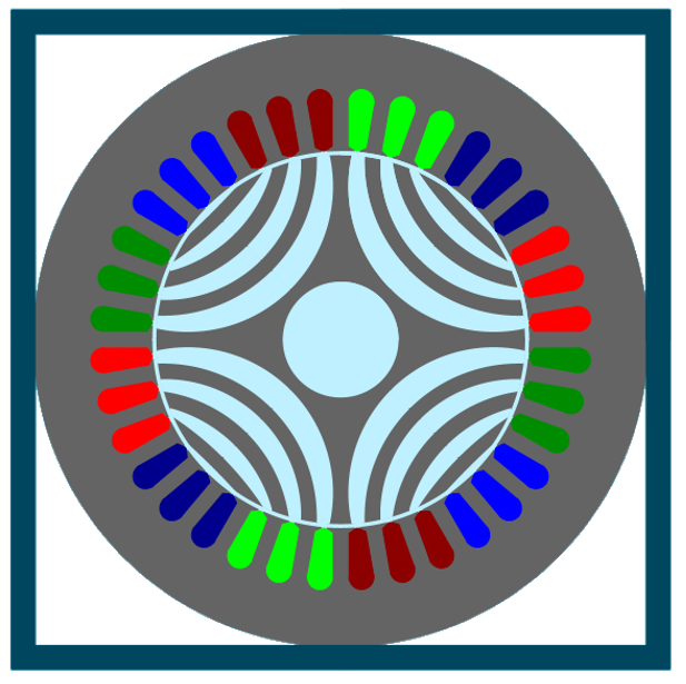
2. Combination between lamination outer shape and frame types
| Frame type | ||||
| None | Circular | Square | ||
|
Lamination outer shape |
None | √ | √ | √ |
| Circular | √ | √ | √ | |
| Square | √ | Not possible | √ | |
 |
 |
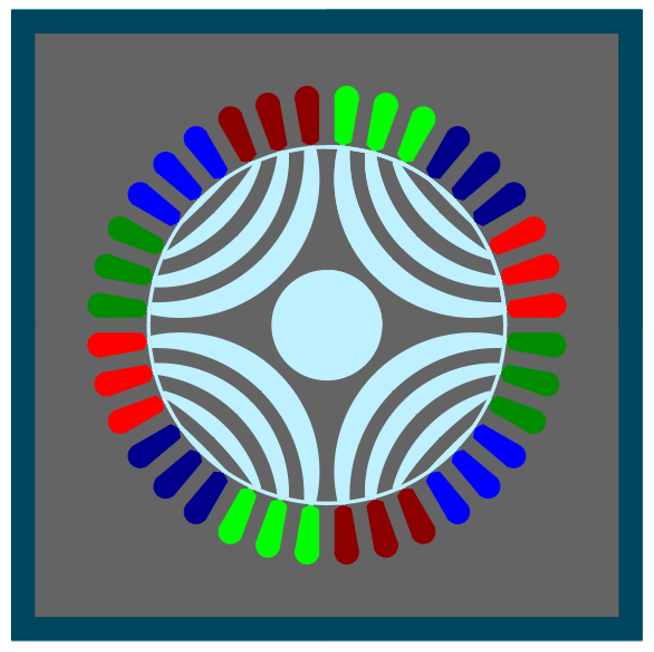 |
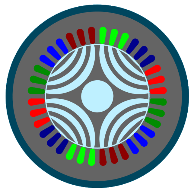
| Circular shape lamination & Circular shape frame | Circular shape lamination & Square shape frame | Square shape lamination & Square shape frame |