In this tutorial, you will create a dome shape at the bottom of the bottle using
morph volumes.
This exercise uses the bottle.hm file, which can be found in the
hm.zip file. Copy the file(s) from this directory to your
working directory. Figure 1.
Open the Model File
In this step you will load the model file,
bottle.hm.
Open the model file, bottle.hm.
Create Morph Volumes
In this step, you will create morph volumes.
From the menu bar, select Morphing > Create > Morph Volumes.
Switch create morphvol to create
matrix.
Set the following:
x density = 3
y density = 8
z density = 5
buffer % = 5
Select elems >> displayed.
Toggle global system to local
system.
For syst, select the system located at the top of the bottle.
Use the default values for the remaining settings.
Click create to create the morph volumes.
Note: Morph volumes are created, encompassing the bottle, with red colored
handles created at the corners of each morph volume.
Click return to exit the panel.
Create Symmetry
In this step, you will create symmetry.
From the menu bar, select Morphing > Create > Symmetries.
Under domains, activate morph volumes & mapping
checkbox.
Change 1 plane to cyclical.
Change 180 degrees to set freq.
Set # of cycles to 8.
For syst select the cylindrical coordinate system located at the top of the
bottle.
Click create.
A cyclical symmetry is created.
Click return to exit the panel.
Create the Dome
In this step you will create the dome.
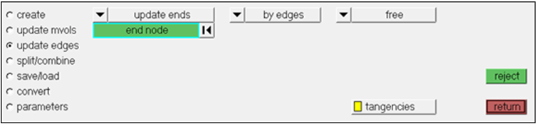
From the menu bar, select Morphing > Create > Morph Volumes and then select the update edges
subpanel.
Toggle update nodes to update
ends.
Change the view to the bottom view by selecting the XY Bottom Plane
View.
Verify that the options by edges and free are selected.
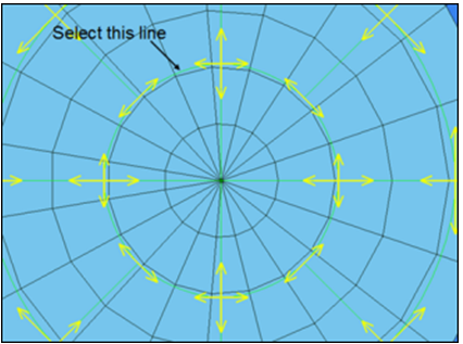
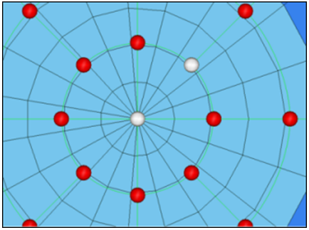
Figure 2.
Using the image below as reference, select the line to the left of the tangency
at the top of the center circle.
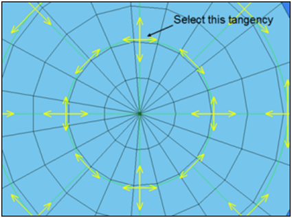
Figure 3.
After selecting the line, select the tangency.
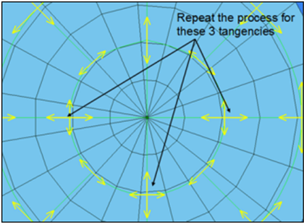
Figure 4.
Repeat Steps 5 and 6 on the three other tangencies shown in the following
image.
Figure 5.
When finished, click return to exit the panel.
From the menu bar, select Morphing > Morph and then select the move handles
subpanel.
Select the handles at the bottom of the bottle as shown in the following
image.
Figure 6.
Switch the morphing method from interactive to
translate.
Switch to along xyz.
Set z val = 10.
Click morph.
Since you have symmetries defined, translating a single handle on the inner
ring at the bottom, ensures that a similar behavior is imparted on all the
handles symmetrically associated to it.
To reduce the number of domains and handles shown on the screen, click the
Mask tab. If this is not displayed, select View > Browsers > HyperMesh > Mask.
Click the - in the Hide column to turn off the display
of all morphing entities.
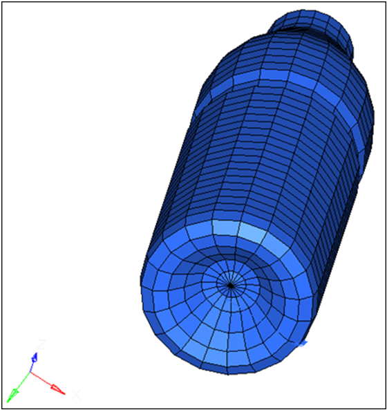
Rotate the model to view the changes made.
Figure 7.
Using morph volumes with appropriate tangencies, and by creating symmetries
you are able to create a dome-shaped feature at the bottom of the bottle.
There are four different methods to define the continuity between the morph
volumes:
Free makes morph volume edges independent of other edges.
Fixed connectivity allows you to prescribe the angle at the end of an
edge.
Main-secondary maintains tangency between two morph volume edges
while keeping the main edge independent of the secondary edge. (When the
main edge moves, the secondary edge follows, but when the secondary edge
moves, the main edge does not have to follow.)
Continuous maintains tangency between two morph volume edges while
allowing both edges to affect each other.
The default setting in morph volume is always set to tangent which is
continuous edge connectivity. This definition can always be changed in the
update edges subpanel, based upon the morphing needs.